Components COMPONENTS ILLUSTRATION 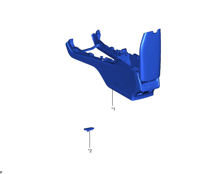
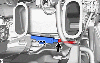
Installation INSTALLATION PROCEDURE 1. INSTALL NO. 1 INDOOR ELECTRICAL KEY ANTENNA ASSEMBLY (a) Engage the clamp to install the No. 1 indoor electrical key antenna assembly. NOTICE: Be careful when installing the No. 1 indoor electrical key antenna assembly. If the No. 1 indoor electrical key antenna assembly is dropped, replace it with a new one. (b) Connect the connector. (c) Connect the front floor carpet assembly. 2. INSTALL CONSOLE ASSEMBLY Click here Removal REMOVAL PROCEDURE 1. REMOVE CONSOLE ASSEMBLY Click here 2. REMOVE NO. 1 INDOOR ELECTRICAL KEY ANTENNA ASSEMBLY (a) Disconnect the front floor carpet assembly.
(c) Disengage the clamp to remove the No. 1 indoor electrical key antenna assembly. NOTICE: Be careful when removing the No. 1 indoor electrical key antenna assembly. If the No. 1 indoor electrical key antenna assembly is dropped, replace it with a new one. |
Toyota Avalon (XX50) 2019-2022 Service & Repair Manual > Sfi System: "E" Camshaft Position Actuator Bank 1 Signal Invalid (P136629)
DESCRIPTION Refer to DTC P001001. Click here DTC No. Detection Item DTC Detection Condition Trouble Area MIL Memory Note P136629 "E" Camshaft Position Actuator Bank 1 Signal Invalid Malfunction in diagnostic signal (VTM) of cam timing control motor with EDU assembly is detected for 3 seconds (1 trip ...