REMOVAL CAUTION / NOTICE / HINT The necessary procedures (adjustment, calibration, initialization, or registration) that must be performed after parts are removed and installed, or replaced during telephone and GPS antenna cord removal/installation are shown below. Necessary Procedure After Parts Removed/Installed/Replaced (for Gasoline Model)
CAUTION: Some of these service operations affect the SRS airbag system. Read the precautionary notices concerning the SRS airbag system before servicing. Click here
 Necessary Procedure After Parts Removed/Installed/Replaced (for HV Model) Necessary Procedure After Parts Removed/Installed/Replaced (for HV Model)
CAUTION: Some of these service operations affect the SRS airbag system. Read the precautionary notices concerning the SRS airbag system before servicing. Click here
PROCEDURE 1. REMOVE LOWER INSTRUMENT PANEL FINISH PANEL LH (for Front Side) Click here
2. REMOVE LOWER INSTRUMENT PANEL FINISH PANEL RH (for Front Side) Click here 3. REMOVE FRONT CONSOLE UPPER PANEL GARNISH (for Front Side) Click here 4. REMOVE CONSOLE BOX POCKET SUB-ASSEMBLY (for Front Side) Click here 5. REMOVE CENTER INSTRUMENT CLUSTER FINISH PANEL SUB-ASSEMBLY (for Front Side) Click here 6. REMOVE CENTER NO. 1 INSTRUMENT CLUSTER FINISH PANEL (for Front Side) Click here 7. REMOVE CENTER NO. 2 INSTRUMENT CLUSTER FINISH PANEL (for Front Side) Click here 8. REMOVE RADIO AND DISPLAY RECEIVER ASSEMBLY WITH BRACKET (for Front Side) Click here 9. REMOVE NO. 2 HEATER TO REGISTER DUCT SUB-ASSEMBLY (for Front Side) Click here 10. REMOVE DCM (TELEMATICS TRANSCEIVER) WITH BRACKET (for Front Side) Click here 11. REMOVE TELEPHONE AND GPS ANTENNA CORD (for Front Side) (a) w/o Navigation System:
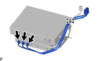
(2) Disconnect the 3 connectors to remove the telephone and GPS antenna cord. (b) w/ Navigation System:
(2) Disconnect the 3 connectors to remove the telephone and GPS antenna cord. 12. REMOVE ROOF HEADLINING ASSEMBLY (for Roof Side) Click here
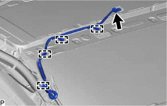
13. REMOVE TELEPHONE AND GPS ANTENNA CORD (for Roof Side)
(b) Disengage the 4 clamps to remove the telephone and GPS antenna cord. | |||||||||||||||||||||||||||||||||||||||||||||||||||||||||
Toyota Avalon (XX50) 2019-2022 Service & Repair Manual > Shift Lever: Inspection
INSPECTION PROCEDURE 1. INSPECT SHIFT LOCK CONTROL ECU HINT: If the results of the following inspections are as specified but a malfunction has occurred, replace the shift lock control unit assembly. (a) Inspect wire harness: (1) Disconnect the shift lock control ECU connector. (2) Measure the volta ...