INSTALLATION PROCEDURE 1. PRECAUTION NOTICE:
2. INSTALL NAVIGATION ECU 3. INSTALL DCM (TELEMATICS TRANSCEIVER) WITH ANTENNA CORD (w/ Manual (SOS) Switch) 4. INSTALL NO. 1 TELEPHONE BRACKET (a) w/o Manual (SOS) Switch: (1) Engage the guide and install the No. 1 telephone bracket with the 2 screws. (b) w/ Manual (SOS) Switch: (1) Engage the 3 guides and install the No. 1 telephone bracket with the 3 screws. 5. INSTALL NO. 2 TELEPHONE BRACKET (a) w/o Manual (SOS) Switch: (1) Engage the guide and install the No. 2 telephone bracket with the 2 screws. (2) Engage the wiring harness clamp. (b) w/ Manual (SOS) Switch: (1) Engage the 3 guides and install the No. 2 telephone bracket with the 3 screws. (2) Engage the wiring harness clamp. (3) Engage the clamp. 6. INSTALL NO. 5 ANTENNA CORD SUB-ASSEMBLY Click here 7. INSTALL NAVIGATION ECU WITH BRACKET (a) w/o Manual (SOS) Switch: (1) Connect each connector. (2) Install the navigation ECU with bracket with the 2 nuts as shown in the illustration. 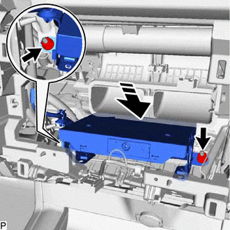
(3) Connect the connector. (b) w/ Manual (SOS) Switch: (1) Connect each connector. (2) Install the navigation ECU with bracket with the 2 nuts as shown in the illustration. 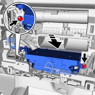
(3) Connect the 2 connectors. 8. INSTALL NO. 2 HEATER TO REGISTER DUCT SUB-ASSEMBLY Click here
9. INSTALL RADIO AND DISPLAY RECEIVER ASSEMBLY WITH BRACKET Click here 10. INSTALL CENTER NO. 2 INSTRUMENT CLUSTER FINISH PANEL Click here 11. INSTALL CENTER NO. 1 INSTRUMENT CLUSTER FINISH PANEL Click here 12. INSTALL CENTER INSTRUMENT CLUSTER FINISH PANEL SUB-ASSEMBLY Click here 13. INSTALL CONSOLE BOX POCKET SUB-ASSEMBLY Click here 14. INSTALL FRONT CONSOLE UPPER PANEL GARNISH Click here 15. INSTALL LOWER INSTRUMENT PANEL FINISH PANEL RH Click here 16. INSTALL LOWER INSTRUMENT PANEL FINISH PANEL LH Click here |
Toyota Avalon (XX50) 2019-2022 Service & Repair Manual > Air Conditioning System(for Gasoline Model): Air Vent cannot be Switched
DESCRIPTION If the air outlet mode does not change even though the air outlet display changes, the following factors may be the cause. Symptom Factor Air outlet mode cannot be changed (air outlet display changes) No. 1 air conditioning radiator damper servo sub-assembly malfunction Damper link disco ...


