DESCRIPTION This circuit is from the skid control ECU (brake actuator assembly) to the radio and display receiver assembly. WIRING DIAGRAM 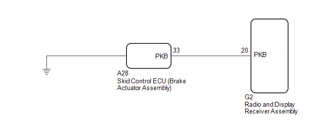 PROCEDURE
(a) Check that the brake warning light comes on when the parking brake is applied and goes off when it is released. OK: The brake warning light operates as specified above.
(a) Disconnect the G2 radio and display receiver assembly connector. (b) Disconnect the A28 skid control ECU (brake actuator assembly) connector. (c) Measure the resistance according to the value(s) in the table below. Standard Resistance:
|
Toyota Avalon (XX50) 2019-2022 Service & Repair Manual > Stop Light Switch: Removal
REMOVAL PROCEDURE 1. REMOVE NO. 1 INSTRUMENT PANEL UNDER COVER SUB-ASSEMBLY Click here 2. REMOVE STOP LIGHT SWITCH ASSEMBLY (a) Disconnect the connector. (b) Turn the stop light switch assembly counterclockwise as shown in the illustration and remove it. Remove in this Direction ...


