DESCRIPTION This circuit includes the navigation ECU and radio and display receiver assembly. WIRING DIAGRAM 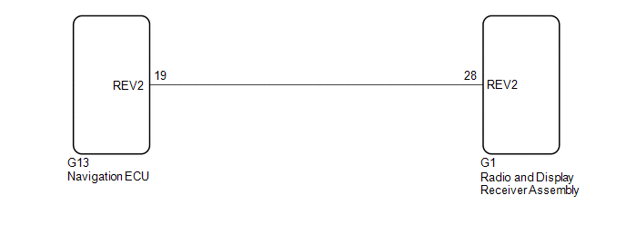 PROCEDURE
(a) Disconnect the G1 radio and display receiver assembly connector. (b) Disconnect the G13 navigation ECU connector. (c) Measure the resistance according to the value(s) in the table below. Standard Resistance:
|
Toyota Avalon (XX50) 2019-2022 Service & Repair Manual > Electronically Controlled Brake System(for Hv Model): Open Circuit in ABS Solenoid Relay Circuit (C146E,C146F)
DESCRIPTION The ABS solenoid relay built into the skid control ECU (brake booster with master cylinder assembly) supplies power to the holding solenoid and reduction solenoid. The ABS solenoid relay is operated 1.5 seconds after the power switch is turned on (IG), and is turned off if an open or sho ...


