DESCRIPTION The radio and display receiver assembly receives a reverse signal from the BKUP LP relay. WIRING DIAGRAM 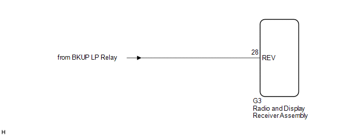 PROCEDURE
(a) Move the shift lever to R and check if the back-up lights come on. OK: The back-up lights come on.
(a) Disconnect the G3 radio and display receiver assembly connector. (b) Measure the voltage according to the value(s) in the table below. Standard Voltage:
|
Toyota Avalon (XX50) 2019-2022 Service & Repair Manual > Smart Key System(for Start Function, Gasoline Model): How To Proceed With Troubleshooting
CAUTION / NOTICE / HINT NOTICE: Do not perform "Smart Code Reset" (all key ID erasure) until all malfunctions and symptoms have been confirmed and resolved. If all key ID erasure is performed without confirming or resolving malfunctions, key registration will be unable to be performed, resulting in ...


