Toyota Avalon Service & Repair Manual: Terminals Of Ecu

TERMINALS OF ECU

HINT:

Check from the rear of the connector while it is connected to the components.

RADIO AND DISPLAY RECEIVER ASSEMBLY

Terminal No. (Symbol)

Wiring Color

Terminal Description

Condition

Specified Condition

G14-1 (FR+) - G3-1 (GND1)

W - BR

Sound signal (Right)

Audio system playing

A waveform synchronized with sound signals is output

G14-2 (FL+) - G3-1 (GND1)

B - BR

Sound signal (Left)

Audio system playing

A waveform synchronized with sound signals is output

G14-3 (RL+) - G3-1 (GND1)

Y - BR

Voice signal

Voice guidance sounding

A waveform synchronized with voice signals is output

G14-6 (FR-) - G3-1 (GND1)

R - BR

Sound signal (Right)

Audio system playing

A waveform synchronized with sound signals is output

G14-7 (FL-) - G3-1 (GND1)

G - BR

Sound signal (Left)

Audio system playing

A waveform synchronized with sound signals is output

G14-8 (RL-) - G3-1 (GND1)

BR - BR

Voice signal

Voice guidance sounding

A waveform synchronized with voice signals is output

G3-1 (GND1) - Body ground

BR - Body ground

Ground

Always

Below 1 V

G3-4 (+B1) - G3-1 (GND1)

R - BR

Power source (+B)

Always

11 to 14 V

G3-5 (TX1+)

B

AVC-LAN communication signal

-

-

G3-6 (TX1-)

W

AVC-LAN communication signal

-

-

G3-10 (AGND) - Body ground

Shield - Body ground

Shield ground

Always

Below 1 V

G3-11 (VAL+) - G3-13 (VA-)

B - R

Sound signal (Left)

External device playing (When stereo jack used)

A waveform synchronized with sound signals is output

G3-12 (VAR+) - G3-13 (VA-)

W - R

Sound signal (Right)

External device playing (When stereo jack used)

A waveform synchronized with sound signals is output

G3-13 (VA-) - G3-1 (GND1)

R - BR

Ground

Always

Below 1 V

G3-14 (ADPG) - G3-1 (GND1)

L - BR

External device connection detection signal

External device connected

Below 1 V

External device not connected

2.1 to 3 V

G3-15 (ACC1) - G3-1 (GND1)

GR - BR

Power source (ACC)

Engine switch off

Below 1 V

Engine switch on (ACC)

11 to 14 V

G3-21 (SW1) - G3-24 (SWG)

W - L

Steering pad switch signal

No switch pushed

2.97 to 3.56 V

Seek+ switch pushed

0.27 to 0.35 V

Seek- switch pushed

0.86 to 1.03 V

Volume+ switch pushed

1.51 to 1.79 V

Volume- switch pushed

2.22 to 2.66 V

G3-22 (SW2) - G3-24 (SWG)

LG - L

Steering pad switch signal

No switch pushed

2.97 to 3.56 V

MODE switch pushed

0.27 to 0.35 V

On/off hook switch pushed

1.51 to 1.79 V

Voice switch pushed

2.22 to 2.66 V

G3-24 (SWG) - G3-1 (GND1)

L - BR

Steering pad switch ground

Always

Below 1 V

G3-25 (MUT1) - G3-1 (GND1)

BE - BR

Mute signal

Audio system playing

2.0 V or higher

Audio system changing modes

Below 1 V

G3-27 (SPD) - G3-1 (GND1)

LG - BR

Vehicle speed signal

See "Check Vehicle Signal" in Operation Check

Click here

-

G3-28 (REV) - G3-1 (GND1)

W - BR

Reverse signal

See "Check Vehicle Signal" in Operation Check

-

G2-5 (CNH1)

L

Local bus communication signal

-

-

G2-6 (CNL1)

W

Local bus communication signal

-

-

G2-13 (CANH)

B

CAN communication signal

-

-

G2-14 (CANL)

W

CAN communication signal

-

-

G2-15 (ILL+) - G3-1 (GND1)

G - BR

Illumination signal

Light control switch off

Below 1 V

Light control switch in tail or head position

11 to 14 V

G2-16 (ILL-) - G3-1 (GND1)

BE - BR

Illumination signal

Light control switch off

Below 1 V

Light control switch in tail or head position

Pulse generation

G2-19 (IG) - G3-1 (GND1)

W - BR

Power source (IG)

Engine switch off

Below 1 V

Engine switch on (IG)

11 to 14 V

G2-20 (PKB) - G3-1 (GND1)

B - BR

Parking brake signal

See "Check Vehicle Signal" in Operation Check

Click here

-

G2-21 (MIN+) - G3-1 (GND1)

SB - BR*1

W - BR*2

Microphone voice signal

See "Check Microphone" in Operation Check

Click here

-

G2-22 (MIN-) - G3-1 (GND1)

V - BR*1

R - BR *2

Microphone voice signal

See "Check Microphone" in Operation Check

Click here

-

G2-23 (MACC) - G3-1 (GND1)*2

B - BR

Microphone power supply

Engine switch off

Below 1 V

Engine switch on (ACC)

4 to 6 V

G2-24 (SGND) - Body ground

Shield - Body ground

Shield ground

Always

Below 1 V

G2-25 (SNS2) - G3-1 (GND1)

BE - BR

Microphone connection detection signal

Always

Below 1 V

G106-1 (USV1)

-

Power source

-

-

G106-2 (US1-)

-

Data signal

-

-

G106-3 (US1+)

-

Data signal

-

-

G106-4 (UGD1)

-

Ground

-

-

G106-5 (USG1)

-

Shield ground

-

-

G111-1 (US4+)

-

USB communication line

-

-

G111-2 (US4-)

-

USB communication line

-

-

G111-3 (UGD4) - Body ground

Shield - Body ground

Shield ground

Always

Below 1 Ω

G110-1 (GV2-)

-

Video signal (Digital)

-

-

G110-2 (GV2+)

-

Video signal (Digital)

-

-

G110-3 (GVG2) - Body ground

Shield - Body ground

Shield ground

Always

Below 1 Ω

G1-7 (SUP) - G3-1 (GND1)

B - BR

Start up signal

20 seconds elapse after turning the engine switch on (ACC)

11 to 14 V

G1-10 (USBV)*1

L

DCM (telematics transceiver) power supply

Engine switch off

Below 1 V

Engine switch on (ACC)

4.75 to 5.25 V

G1-11 (USBG)*1

GR

Ground

-

-

G1-12 (SGND) - Body ground

Shielded - Body ground

Shield ground

Always

Below 1 Ω

G1-19 (RST)*3

R

-

-

-

G1-22 (SI+) - G3-1 (GND1)

SB - BR

Voice signal

Voice guidance sounding

A waveform synchronized with sound is output

G1-23 (SI-) - G3-1 (GND1)

V - BR

Voice signal

Voice guidance sounding

A waveform synchronized with sound is output

G1-24 (SGND) - G3-1 (GND1)

Shielded - BR

Shield ground

Always

Below 1 Ω

G1-25 (MCO+) - G1-26 (MCO-)

W - B

Microphone voice signal

See "Check Microphone (DCU)" in Operation Check

-

G1-26 (MCO-) - G3-1 (GND1)

B - BR

Microphone voice signal

See "Check Microphone (DCU)" in Operation Check

-

G1-28 (REV2) - G3-1 (GND1)

W - BR

Reverse signal

Engine running, shift lever not in R → in R

2 V or less → 11 to 14 V

RA-5 (ANT+) - G3-1 (GND1)

- - BR

Power source of antenna

Engine switch on (ACC)

Radio switch on and FM or AM selected

11 to 14 V

  • *1: w/ Manual (SOS) Switch
  • *2: w/o Manual (SOS) Switch
  • *3: Terminal exists but is not used

NAVIGATION ECU

Terminal No. (Symbol)

Wiring Color

Terminal Description

Condition

Specified Condition

G13-6 (VOI+) - G13-23 (GND)

SB - W-B

Voice signal

Voice guidance sounding

A waveform synchronized with sound is output

G13-7 (VOI-) - G13-23 (GND)

V - W-B

Voice signal

Voice guidance sounding

A waveform synchronized with sound is output

G13-8 (SLD1) - Body ground

Shielded - Body ground

Shield ground

Always

Below 1 Ω

G13-9 (SPD) - G13-23 (GND)

BE - W-B

Vehicle speed signal

See "Check GPS and Vehicle Sensors" in Operation Check

-

G13-10 (+B) - G13-23 (GND)

GR - W-B

Power source (+B)

Always

11 to 14 V

G13-13 (MIC+) - G13-23 (GND)

W - W-B

Microphone voice signal

See "Microphone Check (MEU)" in Operation Check

-

G13-14 (MIC-) - Body ground

B - Body ground

Microphone voice signal

See "Microphone Check (MEU)" in Operation Check

-

G13-19 (REV2) - G13-23(GND)

W - W-B

Reverse signal

Engine running, shift lever not in R → in R

2 V or less → 11 to 14 V

G13-21 (SUP) - G13-23 (GND)

B - W-B

Power source (ACC)

20 seconds elapse after turning the engine switch on (ACC)

11 to 14 V

G13-22 (RST)*2

R

-

-

-

G13-23 (GND) - Body ground

W-B - Body ground

Ground

Always

Below 1 Ω

G113-1 (USB+)*1

-

USB communication line

-

-

G113-2 (USB-)*1

-

USB communication line

-

-

G113-3 (USBS) - Body ground*1

Shielded - Body ground

Shield ground

Always

Below 1 Ω

G109-1 (GVO-)

-

Video signal (Digital)

-

-

G109-2 (GVO+)

-

Video signal (Digital)

-

-

G109-3 (GVG1) - Body ground

Shielded - Body ground

Shield ground

Always

Below 1 Ω

G109-4 (US4+)

-

USB communication line

-

-

G109-5 (US4-)

-

USB communication line

-

-

G109-6 (UGD4) - Body ground

Shielded - Body ground

Shield ground

Always

Below 1 Ω

  • *1: w/ Manual (SOS) Switch
  • *2: Terminal exists but is not used

STEREO COMPONENT AMPLIFIER ASSEMBLY

Terminal No. (Symbol)

Wiring Color

Terminal Description

Condition

Specified Condition

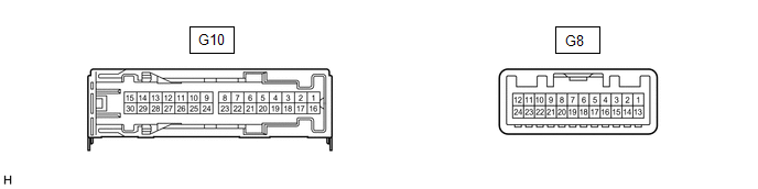
G10-1 (+B) - G10-3 (GND)

L - W-B

Power source (+B)

Always

11 to 14 V

G10-3 (GND) - Body ground

W-B - Body ground

Ground

Always

Below 1 V

G10-5 (WF2+) - G10-3 (GND)

W - W-B

Sound signal (Woofer)

Audio system playing

A waveform synchronized with sound signals is output

G10-6 (WF1+) - G10-3 (GND)

BE - W-B

Sound signal (Woofer)

Audio system playing

A waveform synchronized with sound signals is output

G10-7 (CTR+) - G10-3 (GND)

SB - W-B

Sound signal (Center)

Audio system playing

A waveform synchronized with sound signals is output

G10-8 (TWL+) - G10-3 (GND)

B - W-B

Sound signal (Front Left)

Audio system playing

A waveform synchronized with sound signals is output

G10-9 (TWR+) - G10-3 (GND)

BE - W-B

Sound signal (Front Right)

Audio system playing

A waveform synchronized with sound signals is output

G10-10 (SL+) - G10-3 (GND)

SB - W-B

Sound signal (Rear Left)

Audio system playing

A waveform synchronized with sound signals is output

G10-11 (SR+) - G10-3 (GND)

B - W-B

Sound signal (Rear Right)

Audio system playing

A waveform synchronized with sound signals is output

G10-12 (FL+) - G10-3 (GND)

LG - W-B

Sound signal (Front Left)

Audio system playing

A waveform synchronized with sound signals is output

G10-13 (FR+) - G10-3 (GND)

W - W-B*1

BE - W-B*2

Sound signal (Front Right)

Audio system playing

A waveform synchronized with sound signals is output

G10-14 (RL+) - G10-3 (GND)

B - W-B

Sound signal (Rear Left)

Audio system playing

A waveform synchronized with sound signals is output

G10-15 (RR+) - G10-3 (GND)

R - W-B

Sound signal (Rear Right)

Audio system playing

A waveform synchronized with sound signals is output

G10-16 (+B2) - G10-3 (GND)

B - W-B

Power source (+B)

Always

11 to 14 V

G10-18 (GND2) - Body ground

W-B - Body ground

Ground

Always

Below 1 V

G10-20 (WF2-) - G10-3 (GND)

R - W-B

Sound signal (Woofer)

Audio system playing

A waveform synchronized with sound signals is output

G10-21 (WF1-) - G10-3 (GND)

L - W-B

Sound signal (Woofer)

Audio system playing

A waveform synchronized with sound signals is output

G10-22 (CTR-) - G10-3 (GND)

W - W-B

Sound signal (Center)

Audio system playing

A waveform synchronized with sound signals is output

G10-23 (TWL-) - G10-3 (GND)

GR - W-B

Sound signal (Front Left)

Audio system playing

A waveform synchronized with sound signals is output

G10-24 (TWR-) - G10-3 (GND)

L - W-B

Sound signal (Front Right)

Audio system playing

A waveform synchronized with sound signals is output

G10-25 (SL-) - G10-3 (GND)

P - W-B

Sound signal (Rear Left)

Audio system playing

A waveform synchronized with sound signals is output

G10-26 (SR-) - G10-3 (GND)

Y - W-B

Sound signal (Rear Right)

Audio system playing

A waveform synchronized with sound signals is output

G10-27 (FL-) - G10-3 (GND)

W - W-B

Sound signal (Front Left)

Audio system playing

A waveform synchronized with sound signals is output

G10-28 (FR-) - G10-3 (GND)

B - W-B*1

L - W-B*2

Sound signal (Front Right)

Audio system playing

A waveform synchronized with sound signals is output

G10-29 (RL-) - G10-3 (GND)

LG - W-B

Sound signal (Rear Left)

Audio system playing

A waveform synchronized with sound signals is output

G10-30 (RR-) - G10-3 (GND)

W - W-B

Sound signal (Rear Right)

Audio system playing

A waveform synchronized with sound signals is output

G8-1 (MUTE) - G10-3 (GND)

BE - W-B

Mute signal

Engine switch on (ACC)

Audio system playing

2.0 V or higher

Audio system changing modes

Below 1 V

G8-2 (L-) - G10-3 (GND)

G - W-B

Sound signal (Left)

Audio system playing

A waveform synchronized with sound signals is output

G8-3 (L+) - G10-3 (GND)

B - W-B

Sound signal (Left)

Audio system playing

A waveform synchronized with sound signals is output

G8-4 (R-) - G10-3 (GND)

R - W-B

Sound signal (Right)

Audio system playing

A waveform synchronized with sound signals is output

G8-5 (R+) - G10-3 (GND)

W - W-B

Sound signal (Right)

Audio system playing

A waveform synchronized with sound signals is output

G8-6 (SLD) - Body ground

Shield - Body ground

Shield ground

Always

Below 1 V

G8-7 (TX-)

W

AVC-LAN communication signal

-

-

G8-8 (TX+)

B

AVC-LAN communication signal

-

-

G8-11 (SPD) - G10-3 (GND)

G - W-B

Vehicle speed signal

Engine switch on (IG)

Wheel being rotated

Pulse generation

G8-12 (ACC) - G10-3 (GND)

P - W-B

Power source (ACC)

Engine switch off

Below 1 V

Engine switch on (ACC)

11 to 14 V

G8-14 (II1-) - G10-3 (GND)

BR - W-B

Voice signal

Voice guidance sounding

A waveform synchronized with voice signals is output

G8-15 (II1+) - G10-3 (GND)

Y - W-B

Voice signal

Voice guidance sounding

A waveform synchronized with voice signals is output

G8-18 (SLD1) - Body ground

Shield - Body ground

Shield ground

Always

Below 1 V

G8-24 (TMUT) - Body ground*1

BE - Body ground

Mute signal

Engine switch on (ACC)

Audio system playing

2.0 V or higher

Emergency call mode

Below 1 V

  • *1: w/ Manual (SOS) Switch
  • *2: w/o Manual (SOS) Switch

DCM (TELEMATICS TRANSCEIVER) (w/ Manual (SOS) Switch)

Click here

COMBINATION METER ASSEMBLY

Click here

HEADUP DISPLAY (METER MIRROR SUB-ASSEMBLY)

Click here

SKID CONTROL ECU (BRAKE ACTUATOR ASSEMBLY)

Click here

    System Diagram

    Touch Panel Switch does not Function

    See More:

    Toyota Avalon Service & Repair Manual > Power Window Control System(for Hv Model): Auto Down Operation does not Fully Open Power Window (Catch Protection Function is Activated)
    DESCRIPTION If a door glass does not slide smoothly or a power window regulator motor assembly or door window regulator sub-assembly does not operate smoothly, the catch protection function may be triggered automatically, resulting in the auto down operation being unable to fully open the power wind ...

    Toyota Avalon Owners Manual

    Toyota Avalon Service & Repair Manual

    © 2024 Copyright www.tavalon.net
    0.0187