CALIBRATION NOTICE: When any of the following parts have been replaced, perform adjustment shown in the following table. If not, the intelligent clearance sonar system may not operate correctly. PRECAUTION (PROCEDURE 1) (a) The necessary procedures (adjustment, calibration, initialization or registration) that must be performed after parts are removed and installed, or replaced during intelligent clearance sonar system removal/installation are shown below. For the installation location of the ultrasonic sensors, refer to Parts Location. Click here
PREPARATION (PROCEDURE 2) (a) Preparation
SST: 09989-00020 (b) Confirm levelness of floor surface. (1) Place a bubble level on a level surface and confirm that the bubble is centered. NOTICE: Make sure that there is no gravel, sand, etc., and that the surface is not undulating. HINT: By adjusting the direction of the bubble level, it is possible to find a position where the bubble is centered.  (2) Turn on the digital angle gauge. (3) Place the digital angle gauge in the same location and direction as that of the bubble level where the levelness of the surface was confirmed. NOTICE: Confirm that the location and direction of the digital angle gauge is exactly the same as that of the bubble level. 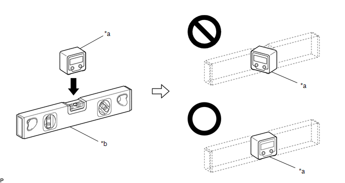
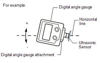
(4) Press the "ZERO" switch to memorize the zero point (perfectly level). NOTICE: Make sure that the digital angle gauge does not move when pressing the switch. If the digital angle gauge moves when the switch is pressed, an incorrect zero point may be memorized and it will not be possible to accurately check for levelness. (5) Using the digital angle gauge in which the zero point (perfectly level) has been memorized, measure the angle of the floor surface at the 4 positions at the front of the vehicle and the 4 positions at the rear of the vehicle as shown in the illustration. Write the measured values into the following worksheet. NOTICE:
HINT: If necessary, the digital angle gauge can be placed anywhere within the specific area when measuring the angle of the floor surface for positions A, C, F and H. 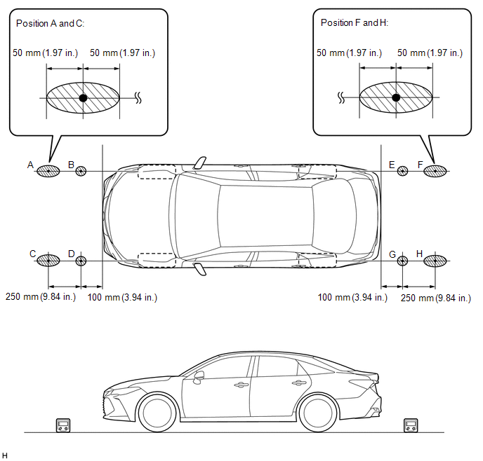
(6) Using the following worksheet, calculate the average of the measurements taken at the 4 positions in front of the vehicle, and calculate the average of the measurements taken at the 4 positions behind the vehicle. Confirm that the front measurement average and the rear measurement average are not more than approximately 0.37 degrees. Also, confirm that the front measurement average and the rear measurement average is less than 0.2 degrees. NOTICE: If the front measurement average and the rear measurement average are more than approximately 0.37 degrees or the difference between the front measurement average and the rear measurement average is 0.2 degrees or more, choose another work area as it is not possible to accurately check the installation angle of the sensors. Worksheet: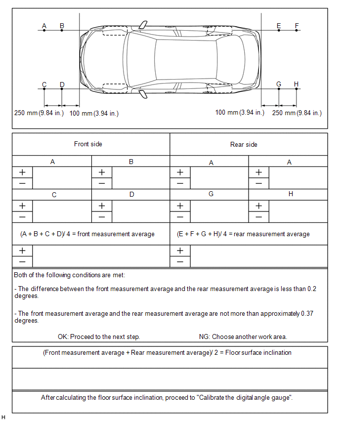 (7) Average the front measurement average and the rear measurement average, then round the answer to 1 decimal place (E.g. 0.0927 degrees is rounded to 0.1 degrees) to obtain the floor surface inclination value. (8) Calibrate the digital angle gauge Adjust the angle of the digital angle gauge until it reads the same value of the floor surface inclination, then press the "ZERO" switch to memorize the zero point (level with floor surface). NOTICE: Before pressing the "ZERO" switch, confirm that the digital angle gauge reading is positive if the floor angle inclination is positive, and negative if the floor angle inclination is negative. 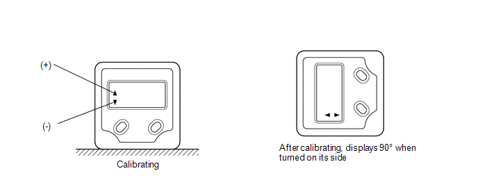 (c) Prepare the digital angle gauge 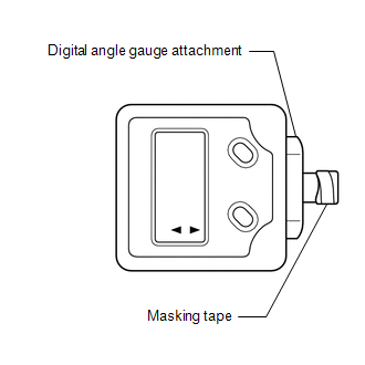 (1) Attach the digital angle gauge attachment to the digital angle gauge. SST: 09989-00020 (2) Attach masking tape to the digital angle gauge attachment. (d) Remove all luggage from the vehicle. (e) Adjust the tire inflation pressure to the specified pressure. Click here (f) Check the height of the vehicle. Click here SENSOR HEIGHT AND ALIGNMENT INSPECTION (PROCEDURE 3) HINT: Check if the installation angle of each ultrasonic sensor is appropriate. (a) Preparation (1) Visually check that the bumper, grill and ultrasonic sensors are installed properly and are not damaged. NOTICE: If the bumper, grill or any ultrasonic sensor is not installed correctly, the calibration may not be able to be completed. (2) Check the tire pressures and adjust them if necessary. Click here
NOTICE:
(b) Sensor height and alignment inspection 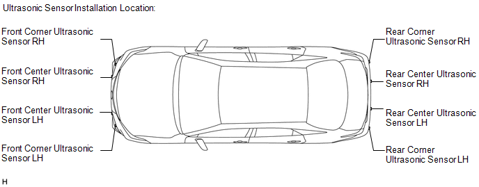 (c) Measure the installation height of the sensors. 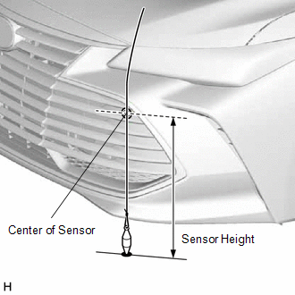 for Bar Type Radiator Grille: Standard Height (Front Bumper):
for Mesh Type Radiator Grille: Standard Height (Front Bumper):
NOTICE: If the installation height of a sensor is not as specified, it may not be possible to measure the sensor angles correctly. If so, unload the vehicle and measure the installation height of the sensors again. HINT: Use the center of the sensor as the measuring point. (d) Using the digital angle gauge, measure the angles of each sensor. Write down the measured values. 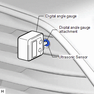 (1) Measure the angle of the front sensors as shown in the illustration. NOTICE: Ensure that the digital angle gauge is flush with the face of the sensor. (2) Measure the angle of the rear sensors. NOTICE: Ensure that the digital angle gauge is flush with the face of the sensor. (3) Confirm that the angles of the sensors are as specified. NOTICE: The sensor angle is the measured sensor angle subtracted from 90°. HINT:
 Standard Angle (Front Bumper):
Standard Angle (Rear Bumper):
(4) If the angle or height of the sensors is not as specified, confirm that the installation is correct and then perform troubleshooting again. REGISTRATION (PROCEDURE 4) (a) Preparation (1) Confirm that the following DTCs are not output.
NOTICE: If DTC C1AEC, C1AED, C1AF0, C1AF3, C1AF4, C1AEA or C168D are output at this point, it is not due to a malfunction. Proceed with the calibration. (b) Connect the Techstream to the DLC3. (c) Turn the engine switch on (IG). (d) Turn the Techstream on. (e) Enter the following menus: Body Electrical / Advanced Parking Guidance/ICS/Intuitive P/A / Utility. Body Electrical > Advanced Parking Guidance/ICS/Intuitive P/A > Utility
(f) According to the display on the Techstream, perform calibration. HINT: If "Battery or Steering Sensor" is selected, further calibration is not required. (Bumper type registration is not required.) (g) Enter the bumper type using the Techstream.
HINT: If the clearance warning ECU assembly is replaced or removed and installed, it is necessary to perform bumper type registration. (h) Using the Techstream, enter the measured sensor values. NOTICE: The sensor angle is the measured sensor angle subtracted from 90°. HINT: The digital angle gauge should indicate 90° when turned on its side. (i) Disconnect the Techstream from the DLC3. |
Toyota Avalon (XX50) 2019-2022 Service & Repair Manual > Roof Antenna: Removal
REMOVAL CAUTION / NOTICE / HINT The necessary procedures (adjustment, calibration, initialization, or registration) that must be performed after parts are removed and installed, or replaced during telephone antenna assembly removal/installation are shown below. Necessary Procedure After Parts Remove ...


