DESCRIPTION This DTC is
stored when there is an open or short circuit in the communication line
between the rear sensors and the ECU, or when there is a malfunction in a
rear sensor. |
DTC No. | Detection Item |
DTC Detection Condition | Trouble Area | |
C1AED | Rear Sensor Communication Malfunction |
An
open or short circuit in the communication line between the rear
sensors and ECU or a malfunction in a rear sensor during initialization
mode after the engine switch is turned on (IG). |
- Rear ultrasonic sensor circuit
- Harness or connector
- Clearance warning ECU assembly
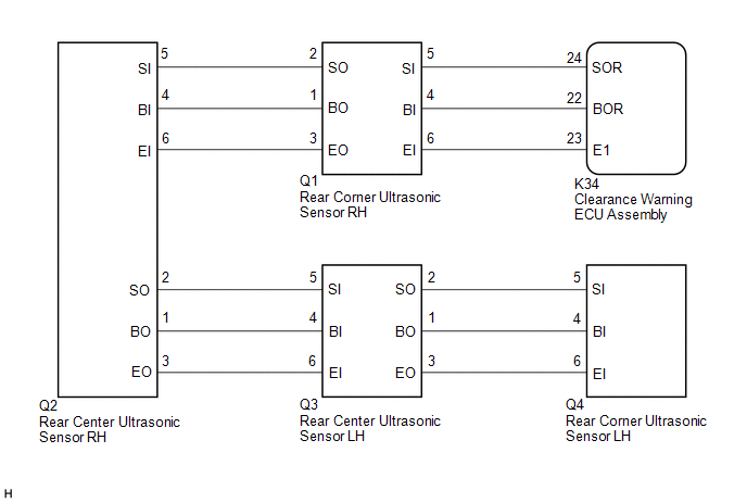
| WIRING DIAGRAM
 PROCEDURE
| 1. |
INITIALIZE REAR CENTER ULTRASONIC SENSOR AND REAR CORNER ULTRASONIC SENSOR |
(a) Initialize the rear center ultrasonic sensor and rear corner ultrasonic sensor.
Click here 
|
NEXT |
 | |
| 2. |
CHECK DTC OUTPUT (C1AED) | (a) Check for DTCs. Body Electrical > Advanced Parking Guidance/ICS/Intuitive P/A > Trouble Codes
(b) Clear the DTCs. Body Electrical > Advanced Parking Guidance/ICS/Intuitive P/A > Clear DTCs
(c) Recheck for DTCs. Body Electrical > Advanced Parking Guidance/ICS/Intuitive P/A > Trouble Codes
|
Result | Proceed to | |
DTC C1AED is output | A | |
No DTCs are output | B |
| B |
 | USE SIMULATION METHOD TO CHECK |
|
A | |
| |
| 3. |
CHECK HARNESS AND CONNECTOR (CLEARANCE WARNING ECU ASSEMBLY - REAR CORNER ULTRASONIC SENSOR RH) |
(a) Disconnect the K34 clearance warning ECU assembly connector. (b) Disconnect the Q1 rear corner ultrasonic sensor RH.
(c) Measure the resistance according to the value(s) in the table below.
Standard Resistance: |
Tester Connection | Condition |
Specified Condition | |
K34-22 (BOR) - Q1-4 (BI) |
Always | Below 1 Ω | |
K34-24 (SOR) - Q1-5 (SI) |
Always | Below 1 Ω | |
K34-23 (E1) - Q1-6 (EI) |
Always | Below 1 Ω | |
K34-22 (BOR) or Q1-4 (BI) - Body ground |
Always | 10 kΩ or higher | |
K34-24 (SOR) or Q1-5 (SI) - Body ground |
Always | 10 kΩ or higher | |
K34-23 (E1) or Q1-6 (EI) - Body ground |
Always | 10 kΩ or higher |
| NG |
| REPAIR OR REPLACE HARNESS OR CONNECTOR |
|
OK | |
| |
| 4. |
CHECK HARNESS AND CONNECTOR (REAR CORNER ULTRASONIC SENSOR RH - REAR CENTER ULTRASONIC SENSOR RH) |
(a) Disconnect the Q2 rear center ultrasonic sensor RH. (b) Measure the resistance according to the value(s) in the table below.
Standard Resistance: |
Tester Connection | Condition |
Specified Condition | |
Q1-1 (BO) - Q2-4 (BI) |
Always | Below 1 Ω | |
Q1-2 (SO) - Q2-5 (SI) |
Always | Below 1 Ω | |
Q1-3 (EO) - Q2-6 (EI) |
Always | Below 1 Ω | |
Q1-1 (BO) or Q2-4 (BI) - Body ground |
Always | 10 kΩ or higher | |
Q1-2 (SO) or Q2-5 (SI) - Body ground |
Always | 10 kΩ or higher | |
Q1-3 (EO) or Q2-6 (EI) - Body ground |
Always | 10 kΩ or higher |
| NG |
| REPAIR OR REPLACE HARNESS OR CONNECTOR |
|
OK | |
| |
| 5. |
CHECK HARNESS AND CONNECTOR (REAR CENTER ULTRASONIC SENSOR RH - REAR CENTER ULTRASONIC SENSOR LH) |
(a) Disconnect the Q3 rear center ultrasonic sensor LH. (b) Measure the resistance according to the value(s) in the table below.
Standard Resistance: |
Tester Connection | Condition |
Specified Condition | |
Q2-1 (BO) - Q3-4 (BI) |
Always | Below 1 Ω | |
Q2-2 (SO) - Q3-5 (SI) |
Always | Below 1 Ω | |
Q2-3 (EO) - Q3-6 (EI) |
Always | Below 1 Ω | |
Q2-1 (BO) or Q3-4 (BI) - Body ground |
Always | 10 kΩ or higher | |
Q2-2 (SO) or Q3-5 (SI) - Body ground |
Always | 10 kΩ or higher | |
Q2-3 (EO) or Q3-6 (EI) - Body ground |
Always | 10 kΩ or higher |
| NG |
| REPAIR OR REPLACE HARNESS OR CONNECTOR |
|
OK | |
| |
| 6. |
CHECK HARNESS AND CONNECTOR (REAR CENTER ULTRASONIC SENSOR LH - REAR CORNER ULTRASONIC SENSOR LH) |
(a) Disconnect the Q4 rear corner ultrasonic sensor LH. (b) Measure the resistance according to the value(s) in the table below.
Standard Resistance: |
Tester Connection | Condition |
Specified Condition | |
Q3-1 (BO) - Q4-4 (BI) |
Always | Below 1 Ω | |
Q3-2 (SO) - Q4-5 (SI) |
Always | Below 1 Ω | |
Q3-3 (EO) - Q4-6 (EI) |
Always | Below 1 Ω | |
Q3-1 (BO) or Q4-4 (BI) - Body ground |
Always | 10 kΩ or higher | |
Q3-2 (SO) or Q4-5 (SI) - Body ground |
Always | 10 kΩ or higher | |
Q3-3 (EO) or Q4-6 (EI) - Body ground |
Always | 10 kΩ or higher |
| NG |
| REPAIR OR REPLACE HARNESS OR CONNECTOR |
|
OK | |
| |
| 7. |
INSPECT REAR CORNER ULTRASONIC SENSOR RH |
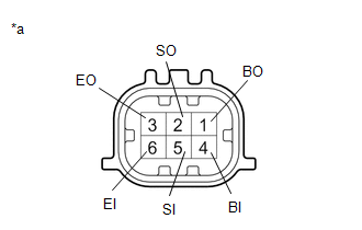
| (a) Measure the resistance according to the value(s) in the table below.
Standard Resistance: |
Tester Connection | Condition |
Specified Condition | |
4 (BI) - 6 (EI) | Always |
10 kΩ or higher | |
4 (BI) - 1 (BO) | Always |
Below 1 Ω | |
5 (SI) - 2 (SO) | Always |
Below 30 Ω | |
6 (EI) - 3 (EO) | Always |
Below 1 Ω | |
 |
|
*a | Component without harness connected
(Rear Corner Ultrasonic Sensor RH) | | |
| NG |
| REPLACE REAR CORNER ULTRASONIC SENSOR RH |
|
OK | |
| |
| 8. |
INSPECT REAR CENTER ULTRASONIC SENSOR RH |
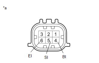
| (a) Measure the resistance according to the value(s) in the table below.
Standard Resistance: |
Tester Connection | Condition |
Specified Condition | |
4 (BI) - 6 (EI) | Always |
10 kΩ or higher | |
4 (BI) - 1 (BO) | Always |
Below 1 Ω | |
5 (SI) - 2 (SO) | Always |
Below 30 Ω | |
6 (EI) - 3 (EO) | Always |
Below 1 Ω | | |
|
|
*a | Component without harness connected
(Rear Center Ultrasonic Sensor RH) | | |
| NG |
| REPLACE REAR CENTER ULTRASONIC SENSOR RH |
|
OK | |
| |
| 9. |
INSPECT REAR CENTER ULTRASONIC SENSOR LH |
| (a) Measure the resistance according to the value(s) in the table below.
Standard Resistance: |
Tester Connection | Condition |
Specified Condition | |
4 (BI) - 6 (EI) | Always |
10 kΩ or higher | |
4 (BI) - 1 (BO) | Always |
Below 1 Ω | |
5 (SI) - 2 (SO) | Always |
Below 30 Ω | |
6 (EI) - 3 (EO) | Always |
Below 1 Ω | | |
|
|
*a | Component without harness connected
(Rear Center Ultrasonic Sensor LH) | | |
| NG |
| REPLACE REAR CENTER ULTRASONIC SENSOR LH |
|
OK | |
| |
| 10. |
INSPECT REAR CORNER ULTRASONIC SENSOR LH |
| (a) Measure the resistance according to the value(s) in the table below.
Standard Resistance: |
Tester Connection | Condition |
Specified Condition | |
4 (BI) - 6 (EI) | Always |
10 kΩ or higher | |
4 (BI) - 1 | Always |
Below 1 Ω | |
5 (SI) - 2 | Always |
Below 30 Ω | |
6 (EI) - 3 | Always |
Below 1 Ω | |
 |
|
*a | Component without harness connected
(Rear Corner Ultrasonic Sensor LH) | | |
| NG |
| REPLACE REAR CORNER ULTRASONIC SENSOR LH |
|
OK | |
| |
| 11. |
REPLACE REAR CORNER ULTRASONIC SENSOR RH |
Click here
|
NEXT | |
| |
| 12. |
CHECK DTC OUTPUT (C1AED) | (a) Clear the DTCs. Body Electrical > Advanced Parking Guidance/ICS/Intuitive P/A > Clear DTCs
(b) Check for DTCs. Body Electrical > Advanced Parking Guidance/ICS/Intuitive P/A > Trouble Codes
|
Result | Proceed to | |
DTC C1AED is output | A | |
No DTCs are output | B |
| B |
| END (REAR CORNER ULTRASONIC SENSOR RH WAS DEFECTIVE) |
|
A | |
| |
| 13. |
REPLACE REAR CENTER ULTRASONIC SENSOR RH |
Click here
|
NEXT | |
| |
| 14. |
CHECK DTC OUTPUT (C1AED) | (a) Clear the DTCs. Body Electrical > Advanced Parking Guidance/ICS/Intuitive P/A > Clear DTCs
(b) Check for DTCs. Body Electrical > Advanced Parking Guidance/ICS/Intuitive P/A > Trouble Codes
|
Result | Proceed to | |
DTC C1AED is output | A | |
No DTCs are output | B |
| B |
| END (REAR CENTER ULTRASONIC SENSOR RH WAS DEFECTIVE) |
|
A | |
| |
| 15. |
REPLACE REAR CENTER ULTRASONIC SENSOR LH |
Click here
|
NEXT | |
| |
| 16. |
CHECK DTC OUTPUT (C1AED) | (a) Clear the DTCs. Body Electrical > Advanced Parking Guidance/ICS/Intuitive P/A > Clear DTCs
(b) Check for DTCs. Body Electrical > Advanced Parking Guidance/ICS/Intuitive P/A > Trouble Codes
|
Result | Proceed to | |
DTC C1AED is output | A | |
No DTCs are output | B |
| B |
| END (REAR CENTER ULTRASONIC SENSOR LH WAS DEFECTIVE) |
|
A | |
| |
| 17. |
REPLACE REAR CORNER ULTRASONIC SENSOR LH |
Click here
|
NEXT | |
| |
| 18. |
CHECK DTC OUTPUT (C1AED) | (a) Clear the DTCs. Body Electrical > Advanced Parking Guidance/ICS/Intuitive P/A > Clear DTCs
(b) Check for DTCs. Body Electrical > Advanced Parking Guidance/ICS/Intuitive P/A > Trouble Codes
|
Result | Proceed to | |
DTC C1AED is output | A | |
No DTCs are output | B |
| A |
| REPLACE CLEARANCE WARNING ECU ASSEMBLY |
| B |
| END (REAR CORNER ULTRASONIC SENSOR LH WAS DEFECTIVE) | | 

