DESCRIPTION This circuit consists of the No. 2 clearance warning buzzer and clearance warning ECU assembly. An ECU-excited type buzzer is used. The ECU operates the buzzers using a sound pattern that changes depending on the distance to the obstacle. WIRING DIAGRAM 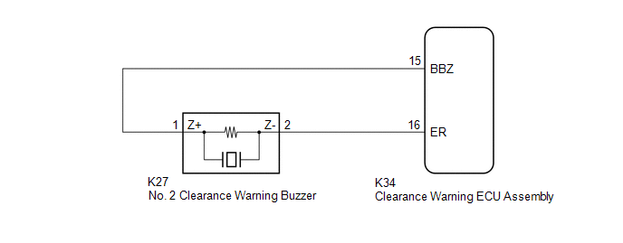 PROCEDURE
(a) Connect the Techstream to the DLC3. (b) Turn the engine switch on (IG). (c) Turn the Techstream on. (d) Enter the following menus: Body Electrical / Advanced Parking Guidance/ICS/Intuitive P/A / Active Test. (e) Check that the rear buzzer operates by performing the Active Test. Body Electrical > Advanced Parking Guidance/ICS/Intuitive P/A > Active Test
OK: The No. 2 clearance warning buzzer sounds.
(a) Disconnect the K34 clearance warning ECU assembly connector. (b) Disconnect the K27 No. 2 clearance warning buzzer connector. (c) Measure the resistance according to the value(s) in the table below. Standard Resistance:
(a) Replace the No. 2 clearance warning buzzer with a new or known good one. Click here
(a) Connect the Techstream to the DLC3. (b) Turn the engine switch on (IG). (c) Turn the Techstream on. (d) Enter the following menus: Body Electrical / Advanced Parking Guidance/ICS/Intuitive P/A / Active Test. (e) Check that the rear buzzer operates by performing the Active Test. Body Electrical > Advanced Parking Guidance/ICS/Intuitive P/A > Active Test
OK: The No. 2 clearance warning buzzer sounds.
|
Toyota Avalon (XX50) 2019-2022 Service & Repair Manual > Meter / Gauge System(for Gasoline Model): Entire Combination Meter does not Operate
DESCRIPTION This circuit is the power source circuit for the combination meter assembly. This circuit provides two types of power sources; one is a constant power source, and the other is an IG power source. WIRING DIAGRAM CAUTION / NOTICE / HINT NOTICE: When replacing the combination meter assembly ...


