REMOVAL CAUTION / NOTICE / HINT
The
necessary procedures (adjustment, calibration, initialization, or
registration) that must be performed after parts are removed, installed,
or replaced during brake actuator assembly removal/installation are
shown below. Necessary Procedures After Parts Removed/Installed/Replaced (for HV Model:) |
Replaced Part or Performed Procedure |
Necessary Procedure | Effect/Inoperative Function when Necessary Procedure not Performed |
Link | |
*: When performing learning using the Techstream.
Click here  | |
Auxiliary battery terminal is disconnected/reconnected |
Perform steering sensor zero point calibration |
Lane Departure Alert System (w/ Steering Control) |
| |
Pre-collision System | |
Intelligent Clearance Sonar System* | |
Lighting System (for HV Model with Cornering Light) | |
Memorize steering angle neutral point |
Parking Assist Monitor System |
| |
Panoramic View Monitor System |
| |
Replacement of brake actuator assembly |
- Bleed air
- Clear the data stored during previous linear solenoid valve offset
learning, ABS holding solenoid valve learning, brake pedal stroke sensor
assembly zero point calibration and system information memorization
- Perform linear solenoid valve offset learning, ABS holding solenoid
valve learning, brake pedal stroke sensor assembly zero point
calibration and system information memorization
|
- DTCs are stored
- ABS warning light illuminates
- Brake warning light / yellow (minor malfunction) illuminates
- Slip indicator light illuminates
- VSC disabled or malfunctions
| for Initialization:
for Calibration:
| |
Operate the electric parking brake switch (electric parking brake switch assembly) |
Parking brake indicator light blinks when the power switch is first turned on (IG) |
|
NOTICE: While
the auxiliary battery is connected, even if the power switch is off,
the brake control system activates when the brake pedal is depressed or
any door courtesy switch turns on. Therefore, when servicing the brake
system components, do not operate the brake pedal or open/close the
doors while the auxiliary battery is connected. PROCEDURE
1. REMOVE BRAKE BOOSTER PUMP ASSEMBLY Click here
2. REMOVE FRONT WHEEL RH Click here
3. SEPARATE FRONT STABILIZER LINK ASSEMBLY RH
HINT: Use the same procedure as for the LH side. Click here
4. REMOVE BRAKE ACTUATOR WITH BRACKET
(a) Release the lock lever and disconnect the connector from the brake actuator assembly.
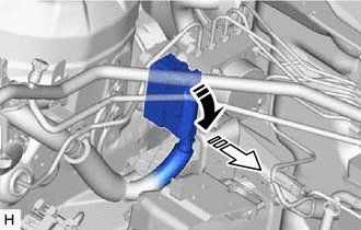
 | Release the lock lever |
 |
Disconnect the connector | NOTICE:
Be careful not to allow any brake fluid to enter the connector.
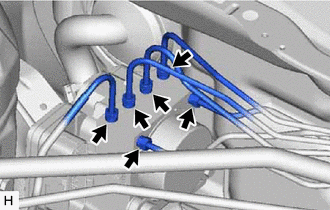
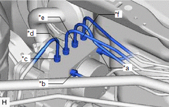
| (b) Use tags or make a memo to identify the places to reconnect the brake lines. |
 |
|
*a | From 1st Chamber of Brake Booster with Master Cylinder Assembly | |
*b | From 2nd Chamber of Brake Booster with Master Cylinder Assembly | |
*c | To Front Wheel Cylinder Assembly RH | |
*d | To Rear Wheel Cylinder Assembly LH | |
*e | To Rear Wheel Cylinder Assembly RH | |
*f | To Front Wheel Cylinder Assembly LH | | |
| (c) Using a union nut wrench, disconnect the 6 brake lines from the brake actuator assembly.
NOTICE:
- Do not kink or damage the brake lines.
- Do not allow any foreign matter such as dirt or dust to enter the brake lines from the connecting parts.
| |
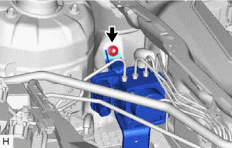
(d) Apply protective tape to the vehicle body as shown in the illustration.
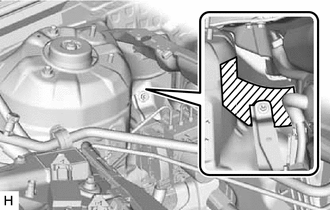
 |
Protective Tape |
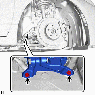
| (e) Remove the 2 bolts. HINT: Insert the tool from the bottom of the vehicle. |
|
(g) Remove the brake actuator with bracket as shown in the illustration.
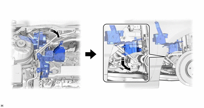
NOTICE:
- Do not kink or damage the brake lines.
- Do not allow any foreign matter such as dirt or dust to enter the brake lines from the connecting parts.
- Be careful not to allow any brake fluid to enter the connector.
- Do not hold the brake actuator assembly by the connector.
- Do not drop the brake actuator with bracket when carrying it.
HINT: Remove the brake actuator with bracket while avoiding the brake lines.
5. REMOVE BRAKE ACTUATOR ASSEMBLY
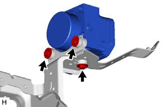
| (a) Remove the 3 bolts and brake actuator assembly from the brake actuator bracket assembly.
NOTICE:
- Do not hold the brake actuator assembly by the connector.
- Do not drop the brake actuator assembly when carrying it.
| |
6. REMOVE BRAKE ACTUATOR BOLT CUSHION
| (a) Remove the 3 brake actuator case collars from the brake actuator bolt cushions. |
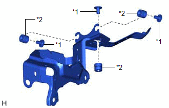 |
|
*1 | Brake Actuator Case Collar | |
*2 | Brake Actuator Bolt Cushion | | |
(b) Remove the 3 brake actuator bolt cushions from the brake actuator bracket assembly. |