Components COMPONENTS ILLUSTRATION 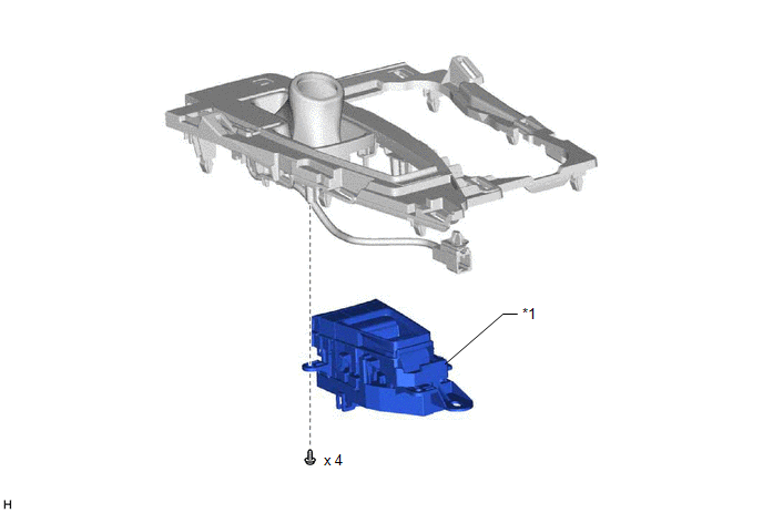
Inspection INSPECTION PROCEDURE 1. INSPECT BRAKE HOLD SWITCH (ELECTRIC PARKING BRAKE SWITCH ASSEMBLY)
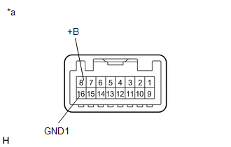
(b) Disconnect the brake hold switch (electric parking brake switch assembly) connector. (c) Check both the connector case and the terminal for deformation and corrosion. OK: No deformation or corrosion. (d) Measure the resistance according to the value(s) in the table below. Standard Resistance:
HINT: If the result is not as specified, replace the brake hold switch (electric parking brake switch assembly). Installation INSTALLATION PROCEDURE 1. INSTALL BRAKE HOLD SWITCH (ELECTRIC PARKING BRAKE SWITCH ASSEMBLY)
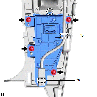
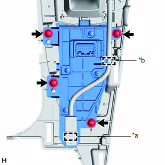
(b) Engage the guide and clamp. 2. INSTALL REAR UPPER CONSOLE PANEL SUB-ASSEMBLY Click here Removal REMOVAL PROCEDURE 1. PRECAUTION Click here 2. REMOVE REAR UPPER CONSOLE PANEL SUB-ASSEMBLY Click here 3. REMOVE BRAKE HOLD SWITCH (ELECTRIC PARKING BRAKE SWITCH ASSEMBLY)
(b) Remove the 4 screws and brake hold switch (electric parking brake switch assembly). |
Toyota Avalon (XX50) 2019-2022 Service & Repair Manual > Stop Light Switch: Components
COMPONENTS ILLUSTRATION *1 NO. 1 INSTRUMENT PANEL UNDER COVER SUB-ASSEMBLY *2 STOP LIGHT SWITCH ASSEMBLY ...