DESCRIPTION The skid control ECU (brake actuator assembly) receives stop light switch assembly signals and uses them to determine whether or not the brakes are applied. The skid control ECU (brake actuator assembly) has a detection circuit that it uses to detect an open in the stop light input line. If the skid control ECU (brake actuator assembly) detects an open in this circuit, it will store this DTC.
WIRING DIAGRAM Ref to DTC C1249. Click here CAUTION / NOTICE / HINT NOTICE:
PROCEDURE
(a) Connect the Techstream to the DLC3. (b) Turn the engine switch on (IG). (c) Enter the following menus: Chassis / ABS/VSC/TRAC/EPB / Data List. Chassis > ABS/VSC/TRAC/EPB > Data List
(d) Take a note of the +BS voltage value. HINT: The noted +BS voltage value is used in a later step.
(a) Inspect the stop light switch assembly. Click here OK: The stop light switch assembly is normal.
(a) Connect the Techstream to the DLC3. (b) Turn the engine switch on (IG). (c) Enter the following menus: Chassis / ABS/VSC/TRAC/EPB / Data List. Chassis > ABS/VSC/TRAC/EPB > Data List
(d) Check that the stop light switch assembly display observed on the Techstream changes according to brake pedal operation. OK: The Techstream displays on or off according to brake pedal operation.
(a) Clear the DTCs. Chassis > ABS/VSC/TRAC/EPB > Clear DTCs(b) Turn the engine switch off. (c) Start the engine. (d) Depress the brake pedal several times to test the stop light circuit. (e) Check if the same DTC is output. Chassis > ABS/VSC/TRAC/EPB > Trouble Codes
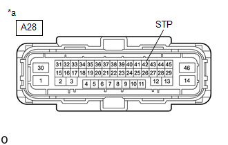
(b) Make sure that there is no looseness at the locking part and the connecting part of the connector. OK: The connector is securely connected. (c) Disconnect the A28 skid control ECU (brake actuator assembly) connector. (d) Check both the connector case and the terminals for deformation and corrosion. OK: No deformation or corrosion. (e) Measure the voltage according to the value(s) in the table below. Standard Voltage:
HINT: *: The minimum voltage value varies depending on the +BS terminal voltage value. The minimum voltage is 85% or more of the +BS terminal voltage.
|
Toyota Avalon (XX50) 2019-2022 Service & Repair Manual > Lane Departure Alert System (w/ Steering Control)(for Hv Model): Vehicle Speed Sensor Circuit (C1AA3)
DESCRIPTION The forward recognition camera receives vehicle speed signals from the skid control ECU (brake booster with master cylinder assembly). If the skid control ECU (brake booster with master cylinder assembly) receives a vehicle speed sensor malfunction signal, it informs the forward recognit ...