DESCRIPTION The skid control ECU (brake actuator assembly) is connected to the combination meter assembly via CAN communication. Pressing the VSC OFF switch turns off TRAC operation, and pressing and holding this switch turns off TRAC and VSC operation. If TRAC and VSC operations are turned off, "Traction Control Turned Off" will be displayed on the multi-information display and the VSC OFF indicator light will come on. WIRING DIAGRAM 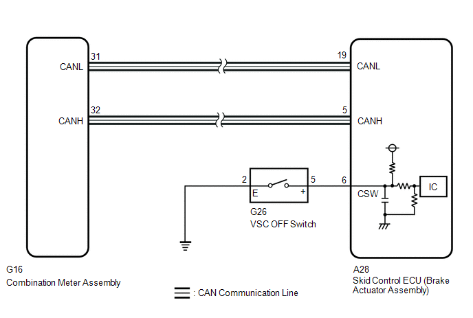 CAUTION / NOTICE / HINT NOTICE: When replacing the skid control ECU (brake actuator assembly), perform system variant learning and acceleration sensor zero point calibration. Click here
PROCEDURE
(a) Check if CAN communication system DTCs are output. Click here
(a) Check if the skid control ECU (brake actuator assembly) connector is securely connected. OK: The connector is securely connected.
(a) Enter the following menus: Chassis / ABS/VSC/TRAC/EPB / Data List. Chassis > ABS/VSC/TRAC/EPB > Data List
(b) Check the indicator light and mode condition on the Techstream changes according to VSC OFF switch operation. Standard:
(a) Enter the following menus: Chassis / ABS/VSC/TRAC/EPB / Active Test. Chassis > ABS/VSC/TRAC/EPB > Active Test
(b) Check that "Traction Control Turned Off" on the multi-information display and the VSC OFF indicator light on the combination meter assembly turn on or off in accordance with the operation of the Techstream. OK: "Traction Control Turned Off" on the multi-information display and the VSC OFF indicator light turn on or off in accordance with the operation of the Techstream.
(a) Turn the engine switch off.
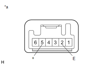
(c) Disconnect the G26 VSC OFF switch connector. (d) Check both the connector case and the terminal for deformation and corrosion. OK: No deformation or corrosion. (e) Measure the resistance according to the value(s) in the table below. Standard Resistance:
(a) Make sure that there is no looseness at the locking part and the connecting part of the connector. OK: The connector is securely connected. (b) Disconnect the A28 skid control ECU (brake actuator assembly) connector. (c) Check both the connector case and the terminals for deformation and corrosion. OK: No deformation or corrosion. (d) Measure the resistance according to the value(s) in the table below. Standard Resistance:
(a) Enter the following menus: Body Electrical / Combination Meter / Active Test. (b) Perform the Active Test of the combination meter assembly using the Techstream. Body Electrical > Combination Meter > Active Test
(c) Check the combination meter assembly. OK: The multi-information display and VSC OFF indicator light turn on or off in accordance with Techstream operation.
|
Toyota Avalon (XX50) 2019-2022 Service & Repair Manual > Exhaust Pipe: Components
COMPONENTS ILLUSTRATION *1 FRONT FLOOR COVER LH *2 FRONT FLOOR COVER RH N*m (kgf*cm, ft.*lbf): Specified torque - - ILLUSTRATION *1 BODY MOUNTING PLATE *2 CENTER FLOOR CROSSMEMBER BRACE *3 FRONT CENTER FLOOR BRACE - - N*m (kgf*cm, ft.*lbf): Specified torque - - ILLUSTRATION *1 FRONT EXHAUST PIPE ASS ...