DESCRIPTION Steering angle sensor signals are input to the skid control ECU (brake booster with master cylinder assembly) via the CAN communication system. HINT: When a malfunction occurs in the communication line to the steering angle sensor, U0126 (Lost Communication With Steering Angle Sensor Module) is output. If a DTC related to the CAN communication line is output, first troubleshoot the CAN communication line. DTCs may be stored if one of the following occurs:
WIRING DIAGRAM 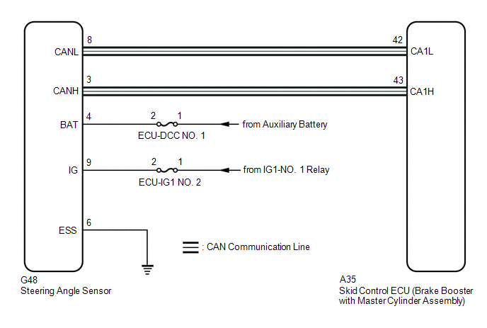 CAUTION / NOTICE / HINT NOTICE: Inspect the fuses for circuits related to this system before performing the following procedure. PROCEDURE
(a) Clear the DTCs. Click here
(b) Turn the power switch off. (c) Turn the power switch on (IG) again and check that no CAN communication system DTCs are output. Click here (d) Turn the power switch on (READY). (e) Drive the vehicle at a speed of 35 km/h (22 mph), turn the steering wheel to the right and left, and check that no speed sensor and/or yaw rate and acceleration sensor DTCs are output. Click here
HINT:
(a) Turn the power switch off. (b) Check that the steering angle sensor has been installed properly. Click here OK: The steering angle sensor installation is normal.
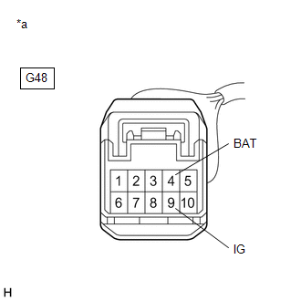
(b) Make sure that there is no looseness at the locking part and the connecting part of the connector. OK: The connector is securely connected. (c) Disconnect the G48 steering angle sensor connector. (d) Check both the connector case and the terminals for deformation and corrosion. OK: No deformation or corrosion. (e) Measure the voltage according to the value(s) in the table below. Standard Voltage:
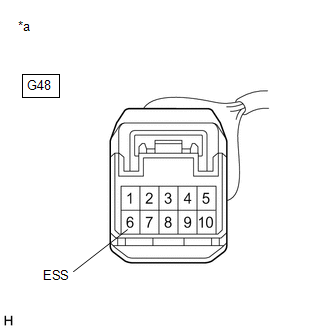
(b) Measure the resistance according to the value(s) in the table below. NOTICE: Before measuring the resistance of the steering angle sensor, turn the power switch off and leave the vehicle for 1 minute or more without operating the key or switches, or opening or closing the doors. Standard Resistance:
|
Toyota Avalon (XX50) 2019-2022 Service & Repair Manual > Brake Booster(for Gasoline Model): Disassembly
DISASSEMBLY PROCEDURE 1. REMOVE BRAKE VACUUM CHECK VALVE ASSEMBLY (a) Remove the brake vacuum check valve assembly from the brake booster assembly. (b) Remove the check valve grommet from the brake booster assembly. 2. REMOVE VACUUM WARNING SWITCH ASSEMBLY (a) Remove the vacuum warning switch assemb ...