REMOVAL CAUTION / NOTICE / HINT The necessary procedures (adjustment, calibration, initialization, or registration) that must be performed after parts are removed, installed, or replaced during brake booster with master cylinder assembly removal/installation are shown below. Necessary Procedures After Parts Removed/Installed/Replaced
NOTICE: While the auxiliary battery is connected, even if the power switch is off, the brake control system activates when the brake pedal is depressed or any door courtesy switch turns on. Therefore, when servicing the brake system components, do not operate the brake pedal or open/close the doors while the auxiliary battery is connected. PROCEDURE 1. PRECAUTION NOTICE: After turning the power switch off, waiting time may be required before disconnecting the cable from the negative (-) auxiliary battery terminal. Therefore, make sure to read the disconnecting the cable from the negative (-) auxiliary battery terminal notices before proceeding with work. Click here 2. PERFORM ACCUMULATOR PRESSURE ZERO DOWN (a) Using the Techstream, perform the accumulator pressure zero down operation. (1) Connect the Techstream to the DLC3 with the power switch off. (2) Turn the power switch on (IG). (3) Turn the Techstream on and enter the following menus: Chassis / ABS/VSC/TRAC / Utility / ECB (Electronically Controlled Brake system) Utility. Chassis > ABS/VSC/TRAC > Utility
(4) Select "Motor Invalid" on the "ECB (Electronically Controlled Brake system) Utility" screen. (5) Perform "Motor Invalid" according to the display on the Techstream. (6) Enter the following menus: Chassis / ABS/VSC/TRAC / Utility / ECB (Electronically Controlled Brake system) Utility. Chassis > ABS/VSC/TRAC > Utility
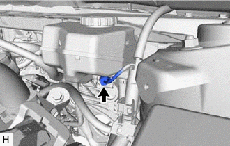
(7) Select "ECB (Electronically Controlled Brake system) Invalid" on the "ECB (Electronically Controlled Brake system) Utility" screen. (8) Perform "ECB (Electronically Controlled Brake system) Invalid" according to the display on the Techstream. (9) Depress the brake pedal 40 times or more to return all the fluid in the accumulator back to the reservoir. HINT: A buzzer may sound due to low accumulator pressure. As this is not a malfunction, continue the procedure. (10) Check that the brake pedal is firm. NOTICE: If the brake pedal is not firm or the pump motor continues to operate even after depressing the brake pedal 40 times or more, the accumulator pressure zero down operation is not complete. (11) Turn the Techstream off and turn the power switch off. (12) Disconnect the Techstream from the DLC3. (13) Disconnect the cable from the negative (-) auxiliary battery terminal. Click here (b) When the accumulator pressure zero down could not be performed using the Techstream. NOTICE: If DTCs are output, the accumulator pressure zero down operation may not be complete. In this case, perform the following procedure. (1) With the power switch off, release the lock lever and disconnect the brake booster pump assembly connector as shown in the illustration. 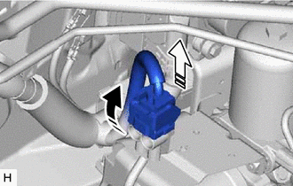
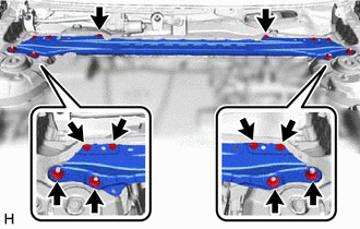
NOTICE: Be careful not to allow any brake fluid to enter the connector. (2) Depress the brake pedal 40 times or more to return all the fluid in the accumulator back to the reservoir. (3) Check that the brake pedal is firm. NOTICE: If the brake pedal is not firm or the pump motor continues to operate even after depressing the brake pedal 40 times or more, the accumulator pressure zero down operation is not complete. (4) Disconnect the cable from the negative (-) auxiliary battery terminal. Click here 3. REMOVE COWL TOP VENTILATOR LOUVER SUB-ASSEMBLY Click here 4. REMOVE FRONT CENTER UPPER SUSPENSION BRACE SUB-ASSEMBLY
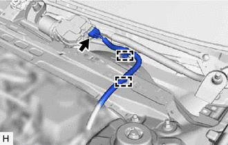
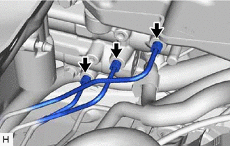
(b) Disengage the 2 clamps and separate the wire harness.
5. DRAIN BRAKE FLUID NOTICE: If brake fluid leaks onto any painted surface, immediately wash it off. 6. DISCONNECT ENGINE ROOM MAIN WIRE
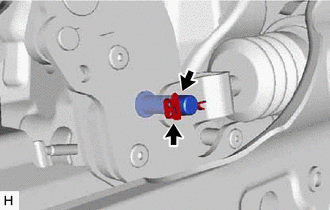
(b) Push the lock arm of the connector to disengage the lock and release the lock lever as shown in the illustration. 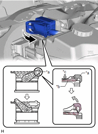
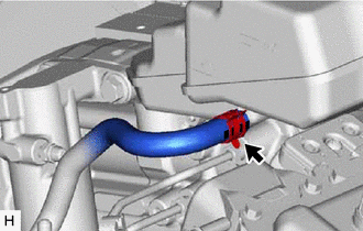
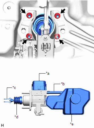
(c) Using a screwdriver, release the pre-lock and disconnect the connector from the brake booster with master cylinder assembly as shown in the illustration. 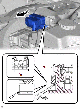
NOTICE: Be careful not to allow any brake fluid to enter the connector. 7. DISCONNECT NO. 1 BRAKE ACTUATOR HOSE
8. DISCONNECT BRAKE LINE
9. REMOVE NO. 1 INSTRUMENT PANEL UNDER COVER SUB-ASSEMBLY Click here
10. REMOVE PUSH ROD PIN
11. REMOVE BRAKE BOOSTER WITH MASTER CYLINDER ASSEMBLY
12. REMOVE BRAKE MASTER CYLINDER GASKET |
Toyota Avalon (XX50) 2019-2022 Service & Repair Manual > Sfi System: A/F (O2) Sensor Signal Biased/Stuck Lean Bank 1 Sensor 1 Circuit Current Above Threshold (P219519,P219524,P219618,P219623)
DESCRIPTION Refer to DTC P003012. Click here HINT: Although the DTC titles say O2 sensor, these DTCs relate to the air fuel ratio sensor (sensor 1). DTC No. Detection Item DTC Detection Condition Trouble Area MIL Memory Note P219519 A/F (O2) Sensor Signal Biased/Stuck Lean Bank 1 Sensor 1 Circuit Cu ...