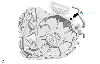
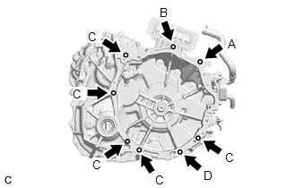
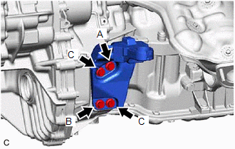
INSTALLATION CAUTION / NOTICE / HINT CAUTION: The engine assembly with hybrid vehicle transaxle assembly is very heavy. Be sure to follow the procedure described in the repair manual, or the engine lifter may suddenly drop. PROCEDURE 1. INSTALL TRANSAXLE CASE PROTECTOR (a) Install the transaxle case protector to the hybrid vehicle transaxle assembly with the clip. (b) Install the 2 bolts. Torque: 10 N·m {102 kgf·cm, 7 ft·lbf} 2. INSTALL STUD BOLT (a) Using a E8 "TORX" socket wrench, install the 2 stud bolts to the hybrid vehicle transaxle assembly. Torque: 30 N·m {306 kgf·cm, 22 ft·lbf} 3. INSTALL TRANSAXLE HOUSING PLUG (a) Install the transaxle housing plug and a new gasket to the hybrid vehicle transaxle assembly. Torque: 39.2 N·m {400 kgf·cm, 29 ft·lbf} 4. INSTALL WIRE HARNESS CLAMP BRACKET (a) Install the 4 wire harness clamp brackets to the hybrid vehicle transaxle assembly with the 4 bolts. 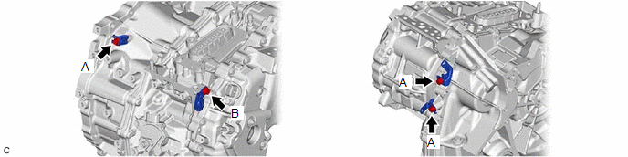 Torque: Bolt (A) : 20 N·m {204 kgf·cm, 15 ft·lbf} Bolt (B) : 30 N·m {306 kgf·cm, 22 ft·lbf} 5. INSTALL TRANSMISSION WIRE (a) Install the transmission wire to the hybrid vehicle transaxle assembly with the bolt. Torque: 13 N·m {133 kgf·cm, 10 ft·lbf} (b) Connect the connector. 6. INSTALL HOSE BRACKET
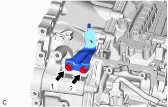
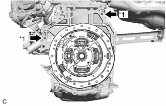
(b) Tighten the 2 bolts in the order shown in the illustration. Torque: 11.5 N·m {117 kgf·cm, 8 ft·lbf} 7. INSTALL NO. 1 TRANSMISSION CONTROL CABLE BRACKET (a) Install the No. 1 transmission control cable bracket to the hybrid vehicle transaxle assembly with the 2 bolts. Torque: 12 N·m {122 kgf·cm, 9 ft·lbf} 8. INSTALL MOTOR COOLING COOLER Click here 9. INSTALL MOTOR CABLE Click here 10. INSTALL HYBRID VEHICLE TRANSAXLE ASSEMBLY
11. INSTALL REAR ENGINE MOUNTING BRACKET
12. INSTALL REAR ENGINE MOUNTING INSULATOR Click here
13. INSTALL FRONT ENGINE MOUNTING BRACKET
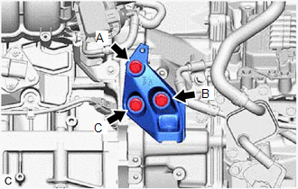
14. INSTALL FRONT ENGINE MOUNTING INSULATOR (a) Install the front engine mounting insulator to the front engine mounting bracket with the bolt. Torque: 72 N·m {734 kgf·cm, 53 ft·lbf} 15. INSTALL FRONT FRAME ASSEMBLY Click here 16. INSTALL FLYWHEEL HOUSING SIDE COVER (a) Install the flywheel housing side cover to the engine assembly. 17. INSTALL STARTER HOLE INSULATOR (a) Install the starter hole insulator to the engine assembly with the 2 bolts. Torque: 46 N·m {469 kgf·cm, 34 ft·lbf} 18. CONNECT HV AIR CONDITIONING WIRE (a) Engage the guide to connect the HV air conditioning wire to the hybrid vehicle transaxle assembly. (b) Install the bolt. Torque: 20 N·m {204 kgf·cm, 15 ft·lbf} 19. CONNECT ENGINE WIRE (a) Install the wire harness to the rack and pinion power steering gear assembly with the 2 bolts. 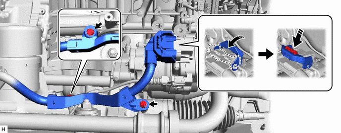 Torque: 10 N·m {102 kgf·cm, 7 ft·lbf} (b) Connect the wire harness connector to the rack and pinion power steering gear assembly. HINT: Make sure that the connector is fully inserted before rotating the lock lever to engage the lock. (c) Connect the 5 clamps. 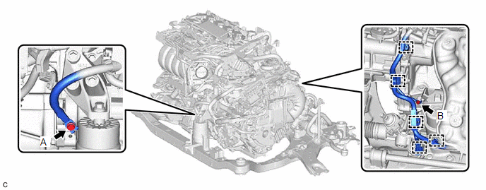
(d) Install the 2 bolts. Torque: Bolt (A) : 20 N·m {204 kgf·cm, 15 ft·lbf} Bolt (B) : 10 N·m {102 kgf·cm, 7 ft·lbf} 20. INSTALL STEERING GEAR HEAT INSULATOR Click here 21. INSTALL ENGINE ASSEMBLY WITH TRANSAXLE Click here 22. PERFORM RESOLVER LEARNING NOTICE: If the hybrid vehicle transaxle assembly has been replaced, make sure to perform resolver learning. Click here |
Toyota Avalon (XX50) 2019-2022 Service & Repair Manual > Rear Door Speaker: Installation
INSTALLATION CAUTION / NOTICE / HINT HINT: Use the same procedure for the RH side and LH side. The following procedure is for the LH side. PROCEDURE 1. INSTALL REAR NO. 2 SPEAKER ASSEMBLY NOTICE: Do not touch the speaker cone. (a) for 8 Speakers: (1) Engage the 3 claws to install the rear No. 2 spea ...