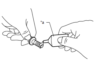
INSTALLATION PROCEDURE 1. INSTALL VVT SENSOR (for Exhaust Side of Bank 2) (a) Apply a light coat of engine oil to the O-ring of the VVT sensor. NOTICE: If reusing the VVT sensor, be sure to inspect the O-ring. (b) Clean the bolt and bolt hole.
(d) Install the VVT sensor to the cylinder head cover sub-assembly LH with the bolt. Torque: 10 N·m {102 kgf·cm, 7 ft·lbf} NOTICE:
(e) Connect the VVT sensor connector. 2. INSTALL VVT SENSOR (for Intake Side of Bank 2) (a) Apply a light coat of engine oil to the O-ring of the VVT sensor. NOTICE: If reusing the VVT sensor, be sure to inspect the O-ring. (b) Clean the bolt and bolt hole.
(d) Install the VVT sensor to the cylinder head cover sub-assembly LH with the bolt. Torque: 10 N·m {102 kgf·cm, 7 ft·lbf} NOTICE:
(e) Connect the VVT sensor connector. 3. INSTALL VVT SENSOR (for Exhaust Side of Bank 1) (a) Apply a light coat of engine oil to the O-ring of the VVT sensor. NOTICE: If reusing the VVT sensor, be sure to inspect the O-ring. (b) Clean the bolt and bolt hole.
(d) Install the VVT sensor to the cylinder head cover sub-assembly with the bolt. Torque: 10 N·m {102 kgf·cm, 7 ft·lbf} NOTICE:
(e) Connect the VVT sensor connector. 4. INSTALL VVT SENSOR (for Intake Side of Bank 1) (a) Apply a light coat of engine oil to the O-ring of the VVT sensor. NOTICE: If reusing the VVT sensor, be sure to inspect the O-ring. (b) Clean the bolt and bolt hole.
(d) Install the VVT sensor to the cylinder head cover sub-assembly with the bolt. Torque: 10 N·m {102 kgf·cm, 7 ft·lbf} NOTICE:
(e) Connect the VVT sensor connector. 5. INSTALL INTAKE AIR SURGE TANK ASSEMBLY Click here 6. INSPECT FOR ENGINE OIL LEAK Click here |
Toyota Avalon (XX50) 2019-2022 Service & Repair Manual > Smart Key System(for Start Function, Gasoline Model): Operation Check
OPERATION CHECK CHECK CUSTOMIZE PARAMETERS (a) The operation check below is based on the non-customized initial condition of the vehicle. Click here CHECK PUSH-BUTTON START FUNCTION (a) Check the push-button start function: (1) Get into the vehicle while carrying the electrical key transmitter sub-a ...