REMOVAL CAUTION / NOTICE / HINT The necessary procedures (adjustment, calibration, initialization or registration) that must be performed after parts are removed and installed, or replaced during VVT sensor removal/installation are shown below. Necessary Procedures After Parts Removed/Installed/Replaced
PROCEDURE 1. REMOVE INTAKE AIR SURGE TANK ASSEMBLY Click here
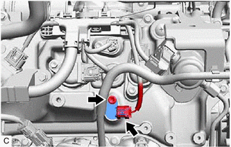
2. REMOVE VVT SENSOR (for Intake Side of Bank 1)
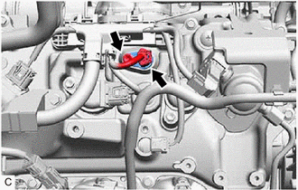
(b) Remove the bolt and VVT sensor from the cylinder head cover sub-assembly. NOTICE: If the VVT sensor has been struck or dropped, replace it. 3. REMOVE VVT SENSOR (for Exhaust Side of Bank 1)
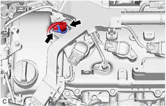
(b) Remove the bolt and VVT sensor from the cylinder head cover sub-assembly. NOTICE: If the VVT sensor has been struck or dropped, replace it. 4. REMOVE VVT SENSOR (for Intake Side of Bank 2)
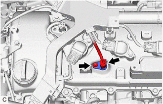
(b) Remove the bolt and VVT sensor from the cylinder head cover sub-assembly LH. NOTICE: If the VVT sensor has been struck or dropped, replace it. 5. REMOVE VVT SENSOR (for Exhaust Side of Bank 2)
(b) Remove the bolt and VVT sensor from the cylinder head cover sub-assembly LH. NOTICE: If the VVT sensor has been struck or dropped, replace it. |
Toyota Avalon (XX50) 2019-2022 Owners Manual > Do-it-yourself
maintenance: Wheels
If a wheel is bent, cracked or heavily corroded, it should be replaced. Otherwise, the tire may separate from the wheel or cause a loss of handling control. Wheel selection When replacing wheels, care should be taken to ensure that they are equivalent to those removed in load capacity, diameter, ri ...