Toyota Avalon Service & Repair Manual: Vehicle Speed Sensor "A" No Signal (P050031)

Toyota Avalon Service & Repair Manual / Engine / 2gr-fks Engine Control / Sfi System / Vehicle Speed Sensor "A" No Signal (P050031)

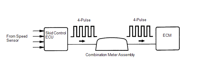
DESCRIPTION

Vehicles, which are equipped with ABS (Anti-lock Brake System), detect the vehicle speed using the skid control ECU (brake actuator assembly) and speed sensor. The speed sensor monitors the wheel rotation speed and sends a signal to the skid control ECU. The skid control ECU converts the wheel speed signal into a 4-pulse signal and transmits it to the ECM via the combination meter assembly. The ECM determines the vehicle speed based on the frequency of the pulse signal.

HINT:

  • Various systems use the vehicle speed signal distributed from the combination meter assembly. Check all the components possibly related to the speed signal.
  • A voltage of 12 V or 5 V is output from each ECU and then input to the combination meter assembly.

    The signal is changed to a pulse signal at the transistor in the combination meter assembly. Each ECU controls the respective system based on the pulse signal.

  • If a short occurs in any of the ECUs or in the wire harness connected to an ECU, all systems using the speed signal will not operate normally.

DTC No.

Detection Item

DTC Detection Condition

Trouble Area

MIL

Memory

Note

P050031

Vehicle Speed Sensor "A" No Signal

While vehicle being driven, no vehicle speed sensor signal transmitted to ECM (2 trip detection logic).

  • Open or short in speed signal circuit
  • Combination meter assembly
  • ECM

Comes on

DTC stored

SAE Code: P0500

MONITOR DESCRIPTION

If there is no speed signal from the combination meter assembly even though the ECM determines that the vehicle is being driven, the ECM interprets this as a malfunction in the speed signal circuit. The ECM then illuminates the MIL and stores this DTC.

MONITOR STRATEGY

Related DTCs

P0500: Vehicle speed sensor verify pulse input

Required Sensors/Components (Main)

Vehicle speed sensor

Combination meter

Skid control ECU

Required Sensors/Components (Related)

Park/neutral position switch

Engine coolant temperature sensor

Crankshaft position sensor

Speed Sensor

Throttle position sensor

Mass air flow meter sub-assembly

Frequency of Operation

Continuous

Duration

5 seconds

MIL Operation

2 driving cycles

Sequence of Operation

None

TYPICAL ENABLING CONDITIONS

All of the following conditions are met

-

Battery voltage

8 V or higher

Engine switch

On (IG)

Starter

Off

Time after engine switch off to on (IG)

3 seconds or more

Engine

Running

Vehicle speed sensor monitor condition

Met

Lost communication with TCM (U0101)

Not detected

TYPICAL MALFUNCTION THRESHOLDS

Vehicle speed sensor signal

No signal

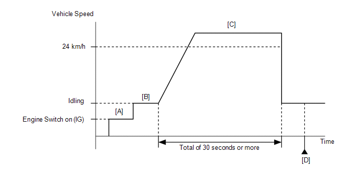
CONFIRMATION DRIVING PATTERN

HINT:

  • After repair has been completed, clear the DTC and then check that the vehicle has returned to normal by performing the following All Readiness check procedure.

    Click here

  • When clearing the permanent DTCs, refer to the "CLEAR PERMANENT DTC" procedure.

    Click here

  1. Connect the Techstream to the DLC3.
  2. Turn the engine switch on (IG).
  3. Turn the Techstream on.
  4. Clear the DTCs (even if no DTCs are stored, perform the clear DTC procedure).
  5. Turn the engine switch off and wait for at least 30 seconds.
  6. Turn the engine switch on (IG) [A].
  7. Turn the Techstream on.
  8. Start the engine [B].
  9. Drive the vehicle at 24 km/h (15 mph) or more for a total of 30 seconds or more [C].

    CAUTION:

    When performing the confirmation driving pattern, obey all speed limits and traffic laws.

  10. Stop the vehicle.
  11. Enter the following menus: Powertrain / Engine / Trouble Codes [D].
  12. Read the pending DTCs.

    HINT:

    • If a pending DTC is output, the system is malfunctioning.
    • If a pending DTC is not output, perform the following procedure.
  13. Enter the following menus: Powertrain / Engine / Utility / All Readiness.
  14. Input the DTC: P050031.
  15. Check the DTC judgment result.

    Techstream Display

    Description

    NORMAL

    • DTC judgment completed
    • System normal

    ABNORMAL

    • DTC judgment completed
    • System abnormal

    INCOMPLETE

    • DTC judgment not completed
    • Perform driving pattern after confirming DTC enabling conditions

    HINT:

    • If the judgment result is NORMAL, the system is normal.
    • If the judgment result is ABNORMAL, the system has a malfunction.
    • If the judgment result is INCOMPLETE, perform steps [C] through [D] again.
    • [A] to [D]: Normal judgment procedure.

      The normal judgment procedure is used to complete DTC judgment and also used when clearing permanent DTCs.

    • When clearing the permanent DTCs, do not disconnect the cable from the battery terminal or attempt to clear the DTCs during this procedure, as doing so will clear the universal trip and normal judgment histories.

WIRING DIAGRAM

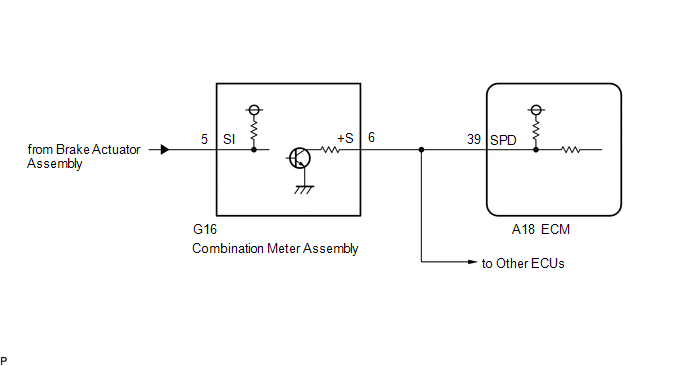
CAUTION / NOTICE / HINT

HINT:

Read freeze frame data using the Techstream. The ECM records vehicle and driving condition information as freeze frame data the moment a DTC is stored. When troubleshooting, freeze frame data can help determine if the vehicle was moving or stationary, if the engine was warmed up or not, if the air fuel ratio was lean or rich, and other data from the time the malfunction occurred.

PROCEDURE

1.

READ VALUE USING TECHSTREAM (VEHICLE SPEED)

(a) Connect the Techstream to the DLC3.

(b) Turn the engine switch on (IG).

(c) Turn the Techstream on.

(d) Enter the following menus: Powertrain / Engine / Data List / Vehicle Speed.

Powertrain > Engine > Data List

Tester Display

Vehicle Speed

(e) Drive the vehicle.

(f) Read the value displayed on the Techstream.

Result

Proceed to

Values displayed on Techstream and speedometer display not equal

A

Values displayed on Techstream and speedometer display equal

B

B

CHECK FOR INTERMITTENT PROBLEMS

A

2.

CHECK HARNESS AND CONNECTOR (COMBINATION METER ASSEMBLY - ECM)

(a) Disconnect the combination meter assembly connector.

(b) Disconnect the ECM connector.

(c) Measure the resistance according to the value(s) in the table below.

Standard Resistance:

Tester Connection

Condition

Specified Condition

G16-6 (+S) - A18-39 (SPD)

Always

Below 1 Ω

NG

REPAIR OR REPLACE HARNESS OR CONNECTOR

OK

3.

CHECK COMBINATION METER SYSTEM

(a) Check the circuits that send vehicle speed signals to this system in the combination meter system.

Click here

NEXT

4.

CLEAR DTC

(a) Connect the Techstream to the DLC3.

(b) Turn the engine switch on (IG).

(c) Turn the Techstream on.

(d) Clear the DTC.

Powertrain > Engine > Clear DTCs

(e) Turn the engine switch off and wait for at least 30 seconds.

NEXT

5.

CONFIRM WHETHER MALFUNCTION HAS BEEN SUCCESSFULLY REPAIRED

(a) Drive the vehicle in accordance with the driving pattern described in Confirmation Driving Pattern.

(b) Enter the following menus: Powertrain / Engine / Trouble Codes.

(c) Read the DTCs.

Powertrain > Engine > Trouble Codes

HINT:

If no DTCs (no pending DTCs) are output to the Techstream, the repair has been successfully completed.

NEXT

END

    Fuel Level Sensor "A" Circuit Short to Battery (P046012,P046014)

    Idle Control System (P050500)

    See More:

    Toyota Avalon Service & Repair Manual > Lighting System(for Hv Model With Cornering Light): Right Headlight ECU Malfunction (B242C,B242D)
    DESCRIPTION The headlight ECU sub-assembly LH or headlight ECU sub-assembly RH stores a DTC if it detects an internal malfunction. DTC No. Detection Item DTC Detection Condition Trouble Area DTC Output from B242C Right Headlight ECU Malfunction The power switch is on (IG). Headlight ECU sub-assembly ...

    Toyota Avalon Owners Manual

    Toyota Avalon Service & Repair Manual

    © 2024 Copyright www.tavalon.net
    0.0188