Toyota Avalon Service & Repair Manual: Starting System

Parts Location

PARTS LOCATION

ILLUSTRATION
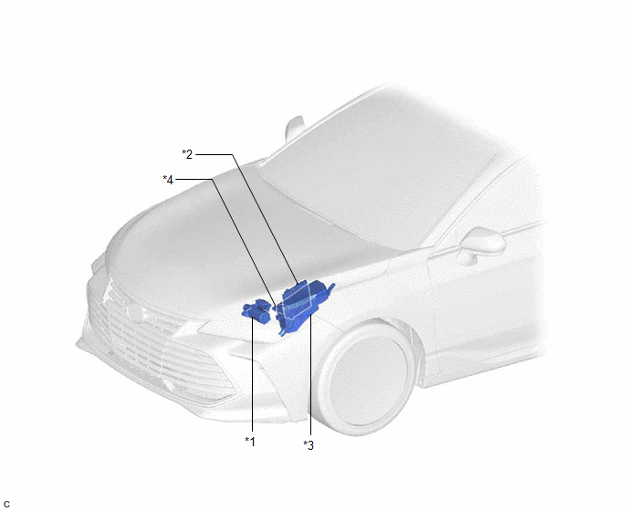
*1

STARTER ASSEMBLY

*2

ECM

*3

ENGINE ROOM RELAY BLOCK AND JUNCTION BLOCK ASSEMBLY

- ST RELAY

- FL MAIN FUSE

- ST FUSE

*4

PARK/NEUTRAL POSITION SWITCH ASSEMBLY

ILLUSTRATION

*1

ENGINE SWITCH

*2

CERTIFICATION ECU (SMART KEY ECU ASSEMBLY)

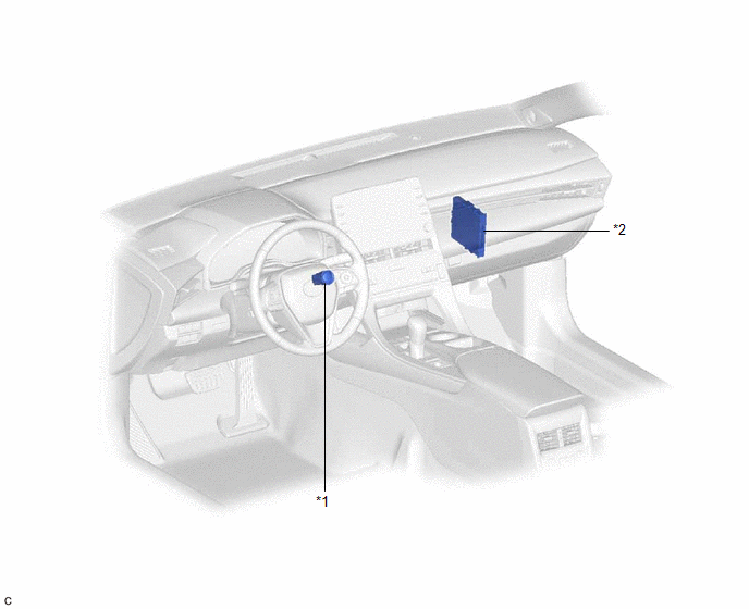
System Diagram

SYSTEM DIAGRAM
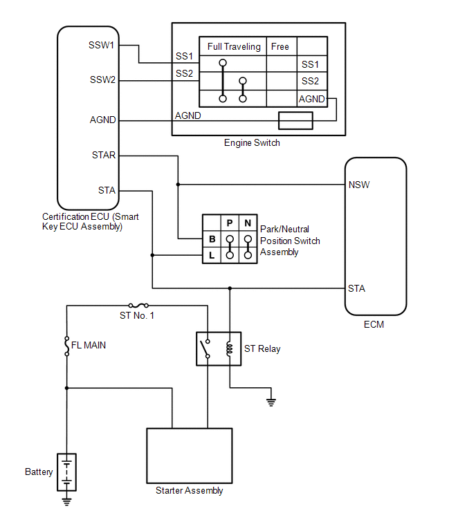
    Removal

    A25a-fxs (emission Control)

    See More:

    Toyota Avalon Service & Repair Manual > Blind Spot Monitor System(for Gasoline Model): Diagnosis System
    DIAGNOSIS SYSTEM DESCRIPTION (a) Blind spot monitor data and Diagnostic Trouble Codes (DTCs) can be read from the Data Link Connector 3 (DLC3) of the vehicle. When the system seems to be malfunctioning, use the Techstream to check for malfunctions and perform repairs. CHECK DLC3 (a) Check the DLC3. ...

    Toyota Avalon Owners Manual

    Toyota Avalon Service & Repair Manual

    © 2023 Copyright www.tavalon.net
    0.0203