ON-VEHICLE INSPECTION PROCEDURE 1. VISUALLY CHECK HOSES, CONNECTIONS AND GASKETS (a) Visually check that the hoses, connections and gaskets have no cracks, leaks or damage. NOTICE:
If any defects are found, replace parts as necessary. 2. INSPECT EVAPORATIVE EMISSION CONTROL SYSTEM CAUTION: To prevent injury due to contact with an operating cooling fan, keep your hands and clothing away from the cooling fans when working in the engine compartment with the engine running or the power switch on (IG). 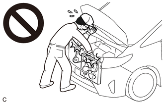 (a) Connect the Techstream to the DLC3. (b) Turn the power switch on (IG). (c) Turn the Techstream on. (d) Put the engine in Inspection Mode (Maintenance Mode). Powertrain > Hybrid Control > Utility
(f) Enter the following menus: Powertrain / Engine / Active Test / Activate the EVAP Purge VSV. Powertrain > Engine > Active Test
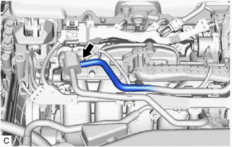
(g) Check that vacuum occurs at the purge valve (purge VSV) port. (h) If vacuum does not occur, check the following items.
(i) Exit Active Test mode and connect the No. 1 fuel vapor feed hose. If the result is not as specified, replace the purge valve (purge VSV), wire harness or ECM. (j) Enter the following menus: Powertrain / Engine / Data List / EVAP (Purge) VSV. Powertrain > Engine > Data List
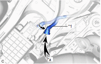
(k) Warm up the engine and drive the vehicle. (l) Confirm that the purge valve (purge VSV) opens. If the result is not as specified, replace the purge valve (purge VSV), wire harness or ECM. 3. CHECK FUEL TANK AND VENT LINE (a) Disconnect the fuel tank vent hose sub-assembly from the fuel vapor containment valve (fuel tank solenoid main valve assembly). 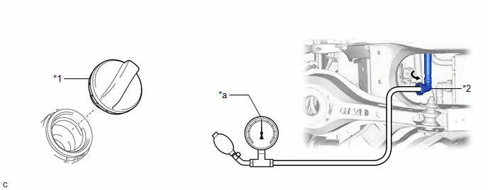
(b) Connect a pressure gauge to the fuel tank vent hose sub-assembly. (c) Apply 4 kPa (0.04 kgf/cm2, 0.6 psi) of pressure to the vent line of the fuel tank assembly. HINT: Perform this inspection with the fuel tank assembly less than 90% full. When the fuel tank assembly is full, the fuel fill check valve closes and the pressure is released through the 2 mm (0.0787 in.) orifice. As a result, when the fuel tank cap assembly is removed, the pressure does not decrease smoothly. (d) Check that the fuel tank assembly pressure is maintained for some time and does not decrease immediately. HINT: If the pressure decreases immediately, one of the following may apply:
(e) Remove the fuel tank cap assembly and check that the pressure is released smoothly. If the pressure is not released smoothly, replace the fuel tank assembly. (f) Connect the fuel tank vent hose sub-assembly to the fuel vapor containment valve (fuel tank solenoid main valve assembly). 4. INSPECT AIR LINE
(b) Check that air flows freely into the air line. If air does not flow freely into the air line, repair or replace the fuel tank vent hose sub-assembly. (c) Connect the fuel tank vent hose sub-assembly to the leak detection pump sub-assembly. |
Toyota Avalon (XX50) 2019-2022 Service & Repair Manual > Brake Actuator(for Hv Model): Removal
REMOVAL CAUTION / NOTICE / HINT The necessary procedures (adjustment, calibration, initialization, or registration) that must be performed after parts are removed, installed, or replaced during brake actuator assembly removal/installation are shown below. Necessary Procedures After Parts Removed/Ins ...