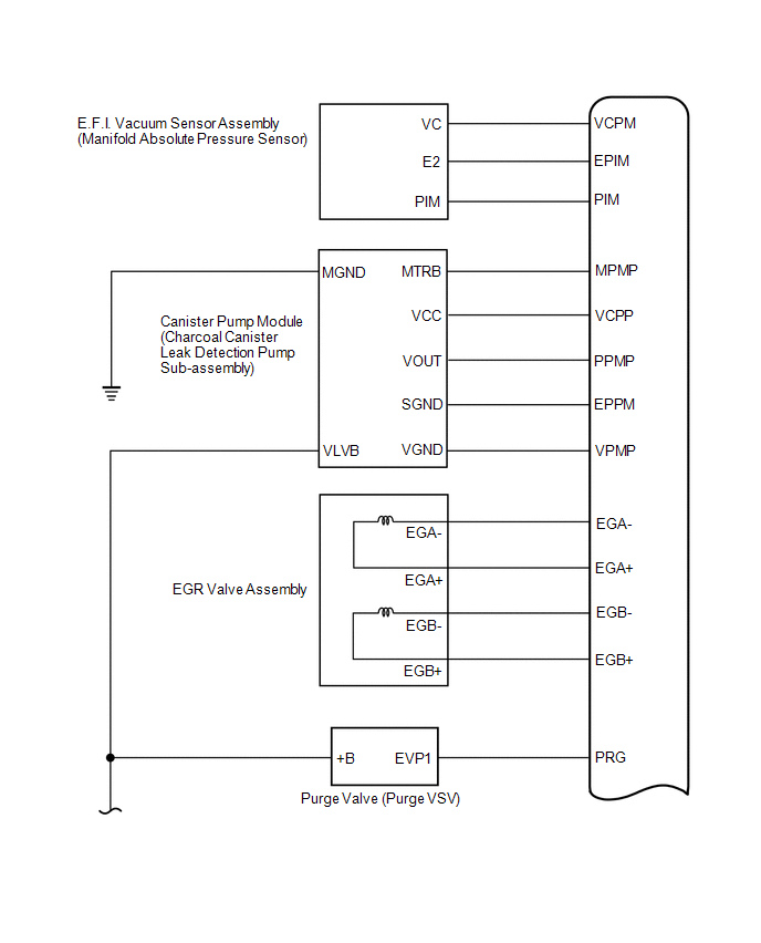
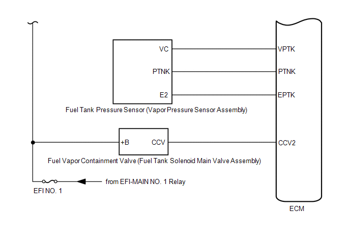
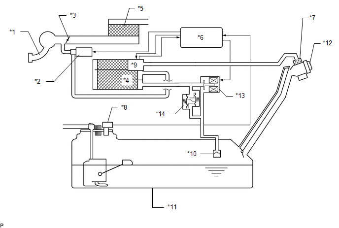
Toyota Avalon Service & Repair Manual: System Diagram

SYSTEM DIAGRAM

*1

Intake Manifold

*2

Purge Valve (Purge VSV)

*3

Throttle Valve

*4

Canister (Charcoal Canister Assembly)

*5

Air Cleaner

*6

ECM

*7

Canister Filter

*8

Fuel Tank Pressure Sensor

(Vapor Pressure Sensor Assembly)

*9

Canister Pump Module

(Charcoal Canister Leak Detection Pump Sub-assembly)

- Canister Pressure Sensor

- Pump Motor

- Vent Valve

*10

Cut-off Valve

*11

Fuel Tank Assembly

*12

Fuel Tank Cap Assembly

*13

Fuel Vapor Containment Valve

(Fuel Tank Solenoid Main Valve Assembly)

*14

Fuel Outlet Valve (Relief Valve)

    Parts Location

    Fuel Tank Cap

    See More:

    Toyota Avalon Service & Repair Manual > Brake Actuator(for Hv Model): Removal
    REMOVAL CAUTION / NOTICE / HINT The necessary procedures (adjustment, calibration, initialization, or registration) that must be performed after parts are removed, installed, or replaced during brake actuator assembly removal/installation are shown below. Necessary Procedures After Parts Removed/Ins ...

    Toyota Avalon Owners Manual

    Toyota Avalon Service & Repair Manual

    © 2023 Copyright www.tavalon.net
    0.0183