Toyota Avalon Service & Repair Manual: Power Source Circuit

DESCRIPTION

This circuit is the power source circuit for the stereo component equalizer assembly.

WIRING DIAGRAM

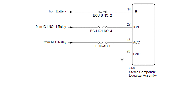
CAUTION / NOTICE / HINT

NOTICE:

Inspect the fuses and relays for circuits related to this system before performing the following procedure.

PROCEDURE

1.

CHECK HARNESS AND CONNECTOR (STEREO COMPONENT EQUALIZER ASSEMBLY - BATTERY [+B, IGN] AND BODY GROUND)

(a) Disconnect the stereo component equalizer assembly connector.

*a

Front view of wire harness connector

(to Stereo Component Equalizer Assembly)

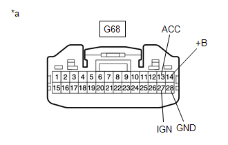
(b) Measure the voltage according to the value(s) in the table below.

Standard Voltage:

Tester Connection

Condition

Specified Condition

G68-14 (+B) - Body ground

Always

11 to 14 V

G68-27 (IGN) - Body ground

Engine switch on (IG)

11 to 14 V

G68-13 (ACC) - Body ground

Engine switch on (ACC)

11 to 14 V

(c) Measure the resistance according to the value(s) in the table below.

Standard Resistance:

Tester Connection

Condition

Specified Condition

G68-28 (GND) - Body ground

Always

Below 1 Ω

OK

PROCEED TO NEXT SUSPECTED AREA SHOWN IN PROBLEM SYMPTOMS TABLE

NG

REPAIR OR REPLACE HARNESS OR CONNECTOR

    Parts Location

    Precaution

    See More:

    Toyota Avalon Service & Repair Manual > Electric Parking Brake System(for Hv Model): Data List / Active Test
    DATA LIST / ACTIVE TEST READ DATA LIST HINT: Using the Techstream to read the Data List allows the values or states of switches, sensors, actuators and other items to be read without removing any parts. This non-intrusive inspection can be very useful because intermittent conditions or signals may b ...

    Toyota Avalon Owners Manual

    Toyota Avalon Service & Repair Manual

    © 2024 Copyright www.tavalon.net
    0.0118