INSTALLATION PROCEDURE 1. INSTALL ROOF HEADLINING ASSEMBLY
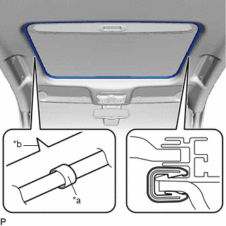
(b) Put the roof headlining assembly into the vehicle through the front door RH as shown in the illustration. 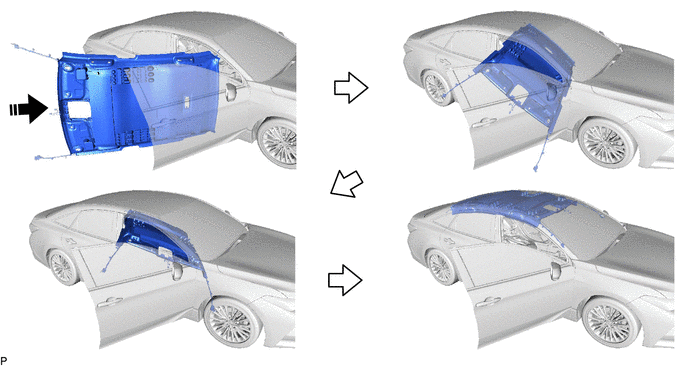
NOTICE: Do not damage the roof headlining assembly or vehicle interior. (c) for Roof Side (for Normal Roof): (1) Engage the 2 claws to install the base of each visor holder. 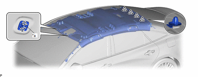
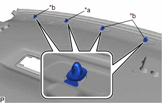
(2) Engage the 4 clips and install the roof headlining assembly. (d) for Roof Side (for Moon Roof): (1) Engage the 2 claws to install the base of each visor holder. 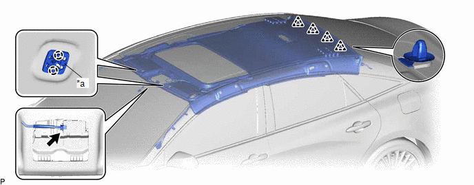
(2) Engage the 4 clips and install the roof headlining assembly. (3) Connect the connector. (e) for Rear Pillar LH Side: (1) Engage the guide. (2) Connect the connector. (f) for Rear Pillar RH Side: (1) Engage the guide. (2) Connect each connector. (g) for Front Pillar LH Side: (1) Remove the protective cover. (2) Engage the 4 clamps. (3) Connect the 2 connectors. (4) Install the protective cover. (h) for Front Pillar RH Side: (1) Remove the protective cover. (2) Engage the 2 clamps. (3) Engage the guide. (4) Connect the connector bracket with the bolt. (5) Install the protective cover. (i) for Windshield Glass Side: (1) Connect each connector. 2. INSTALL SUN ROOF OPENING TRIM MOULDING (for Moon Roof)
3. INSTALL VISOR HOLDER LH (a) Install the visor holder LH as shown in the illustration. 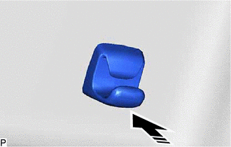
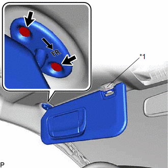
4. INSTALL VISOR ASSEMBLY LH NOTICE: Make sure to install the visor assembly LH with its arrow facing the front of the vehicle. (a) Connect the connector.
(c) for "TORX" Screw: (1) Using a T25 "TORX" socket wrench, install the visor assembly LH with the 2 screws. (d) except "TORX" Screw: (1) Install the visor assembly LH with the 2 screws. 5. INSTALL VISOR BRACKET COVER LH (a) Engage the 4 claws to install the visor bracket cover LH. 6. INSTALL VISOR HOLDER RH HINT: Use the same procedure as for the LH side. 7. INSTALL VISOR ASSEMBLY RH HINT: Use the same procedure as for the LH side. 8. INSTALL VISOR BRACKET COVER RH HINT: Use the same procedure as for the LH side. 9. INSTALL ASSIST GRIP SUB-ASSEMBLY HINT: Use the same procedure for all assist grip sub-assemblies.
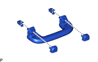
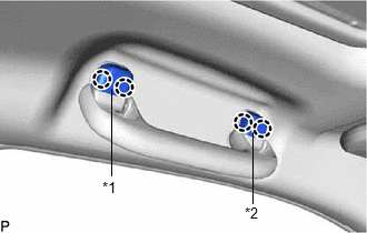
(b) Temporarily install the 2 assist grip covers to the assist grip as shown in the illustration. (c) Engage the 2 clips to install the assist grip sub-assembly as shown in the illustration. 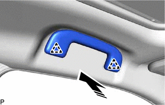
10. INSTALL REAR ASSIST GRIP ASSEMBLY LH HINT: Use the same procedure as for the assist grip sub-assembly. 11. INSTALL REAR ASSIST GRIP ASSEMBLY RH HINT: Use the same procedure as for the assist grip sub-assembly. 12. INSTALL NO. 1 FORWARD RECOGNITION COVER Click here
13. INSTALL NO. 2 FORWARD RECOGNITION COVER Click here 14. INSTALL AIR CONDITIONING THERMISTOR ASSEMBLY (w/ Humidity Sensor) Click here 15. INSTALL SENSOR COVER (w/ Humidity Sensor) Click here 16. INSTALL SPOT LIGHT ASSEMBLY Click here 17. INSTALL ROOF CONSOLE BOX ASSEMBLY Click here 18. INSTALL TRANSMISSION FLOOR SHIFT ASSEMBLY for UA80E: Click here for P710: Click here
19. INSTALL INSTRUMENT PANEL SAFETY PAD SUB-ASSEMBLY Click here 20. INSTALL ROOF SIDE INNER GARNISH LH (a) Install 3 new clips to the roof side inner garnish LH. (b) Engage the guide as shown in the illustration. 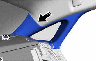
(c) Engage the 3 clips to install the roof side inner garnish LH as shown in the illustration. 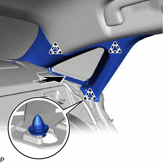
21. INSTALL ROOF SIDE RAIL GARNISH ASSEMBLY LH (a) Engage the 3 guides and 3 claws as indicated by the arrows, in the order shown in the illustration to install the roof side rail garnish assembly LH. 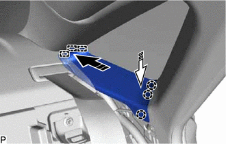
22. INSTALL CENTER PILLAR UPPER GARNISH LH (a) Install a new clip to the center pillar upper garnish LH. (b) Engage the 3 guides and clip as shown in the illustration. 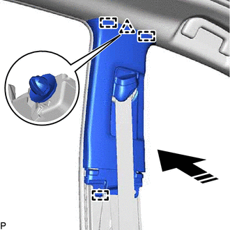
(c) Install the center pillar upper garnish LH with the 2 clips. 23. INSTALL CENTER PILLAR LOWER GARNISH LH (a) Engage the 2 claws and 3 clips to install the center pillar lower garnish LH as shown in the illustration. 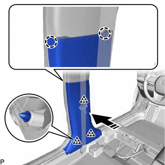
24. CONNECT FRONT SEAT OUTER BELT ASSEMBLY LH Click here 25. INSTALL LAP BELT OUTER ANCHOR COVER (for LH Side) Click here 26. INSTALL REAR DOOR OPENING TRIM WEATHERSTRIP LH Click here 27. INSTALL REAR DOOR SCUFF PLATE LH (for Gasoline Model) (a) Engage the guide and 6 claws to install the rear door scuff plate LH as shown in the illustration. 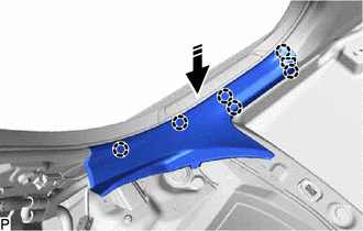
28. INSTALL REAR DOOR SCUFF PLATE LH (for HV Model) (a) Engage the guide, 6 claws and clip to install the rear door scuff plate LH as shown in the illustration. 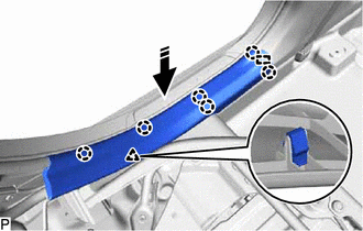
29. INSTALL FRONT PILLAR GARNISH LH (a) Remove the protective cover.
(c) w/o Front No. 3 Speaker: (1) Push the front pillar garnish LH as shown in the illustration to engage the 2 guides. 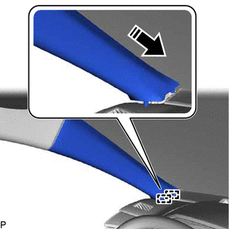
(d) w/ Front No. 3 Speaker: (1) Connect the connector. (2) Push the front pillar garnish LH as shown in the illustration to engage the 2 guides. (e) Engage the 2 front pillar garnish clips to install the front pillar garnish LH as shown in the illustration. HINT: Make sure that the curtain shield airbag assembly LH is not pinched. 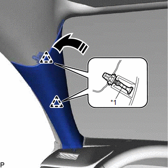
30. INSTALL FRONT DOOR OPENING TRIM WEATHERSTRIP LH Click here 31. INSTALL COWL SIDE TRIM SUB-ASSEMBLY LH (a) Engage the claw and clip as shown in the illustration. 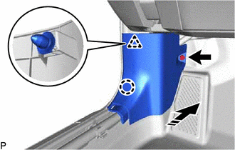
(b) Install the cowl side trim sub-assembly LH with the clip. 32. INSTALL FRONT DOOR SCUFF PLATE LH (a) Engage the guide and 10 claws to install the front door scuff plate LH as shown in the illustration. 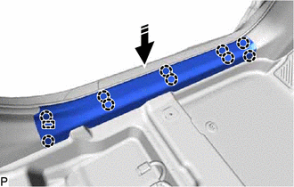
33. INSTALL ROOF SIDE INNER GARNISH RH HINT: Use the same procedure as for the LH side. 34. INSTALL ROOF SIDE RAIL GARNISH ASSEMBLY RH HINT: Use the same procedure as for the LH side. 35. INSTALL CENTER PILLAR UPPER GARNISH RH HINT: Use the same procedure as for the LH side. 36. INSTALL CENTER PILLAR LOWER GARNISH RH HINT: Use the same procedure as for the LH side. 37. CONNECT FRONT SEAT OUTER BELT ASSEMBLY RH HINT: Use the same procedure as for the LH side. 38. INSTALL LAP BELT OUTER ANCHOR COVER (for RH Side) HINT: Use the same procedure as for the LH side. 39. INSTALL REAR DOOR OPENING TRIM WEATHERSTRIP RH HINT: Use the same procedure as for the LH side. 40. INSTALL REAR DOOR SCUFF PLATE RH HINT: Use the same procedure as for the LH side. 41. INSTALL FRONT PILLAR GARNISH RH HINT: Use the same procedure as for the LH side. 42. INSTALL FRONT DOOR OPENING TRIM WEATHERSTRIP RH HINT: Use the same procedure as for the LH side. 43. INSTALL COWL SIDE TRIM SUB-ASSEMBLY RH HINT: Use the same procedure as for the LH side. 44. INSTALL FRONT DOOR SCUFF PLATE RH HINT: Use the same procedure as for the LH side. 45. INSTALL REAR SEAT ASSEMBLY Click here 46. INSTALL FRONT SEAT ASSEMBLY Click here |
Toyota Avalon (XX50) 2019-2022 Service & Repair Manual > Can Communication System(for Gasoline Model): Open in One Side of Bus 4 Branch Line
DESCRIPTION When the CAN bus main lines are normal (no open, short to ground, short to +B or short between lines) and there is an ECU or sensor on the "Communication Bus Check" screen that is indicated as not communicating or whose connection status on the "Communication Bus Check" screen changes in ...