Components COMPONENTS ILLUSTRATION 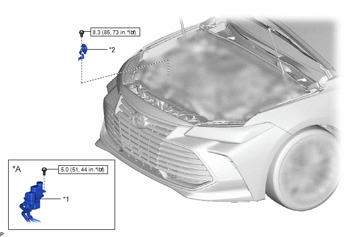
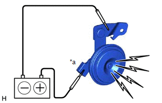
Inspection INSPECTION PROCEDURE 1. INSPECT SECURITY HORN ASSEMBLY
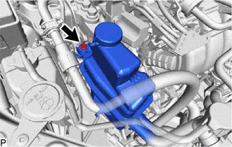
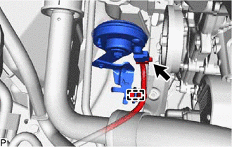
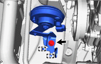
Installation INSTALLATION PROCEDURE 1. INSTALL SECURITY HORN ASSEMBLY (a) Engage the 2 guides and install the security horn assembly with the bolt. Torque: 8.3 N·m {85 kgf·cm, 73 in·lbf} (b) Connect the connector. (c) Engage the clamp. 2. INSTALL INVERTER RESERVE TANK SUB-ASSEMBLY (for HV Model) (a) Engage the pin as shown in the illustration. 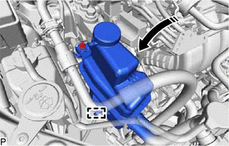
(b) Install the inverter reserve tank assembly with the bolt. Torque: 5.0 N·m {51 kgf·cm, 44 in·lbf} Removal REMOVAL PROCEDURE 1. SEPARATE INVERTER RESERVE TANK SUB-ASSEMBLY (for HV Model)
(b) Disengage the pin to separate the inverter reserve tank assembly from the engine mounting insulator sub-assembly RH as shown in the illustration. 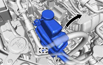
NOTICE:
2. REMOVE SECURITY HORN ASSEMBLY
(b) Disconnect the connector.
(d) Disengage the 2 guides to remove the security horn assembly. |
Toyota Avalon (XX50) 2019-2022 Service & Repair Manual > Lighting (ext): High Mounted Stop Light Assembly
ComponentsCOMPONENTS ILLUSTRATION *1 CENTER STOP LIGHT SET - - InspectionINSPECTION PROCEDURE 1. INSPECT CENTER STOP LIGHT SET *a Component without harness connected (Center Stop Light Set) (a) Apply auxiliary battery voltage to the center stop light set and check that the light illuminates. OK: Me ...