DESCRIPTION This circuit provides power to operate the clearance warning ECU assembly. WIRING DIAGRAM 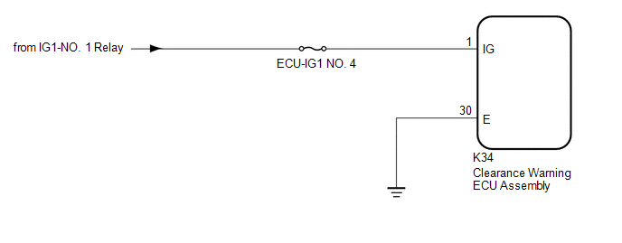 CAUTION / NOTICE / HINT NOTICE: Inspect the fuses for circuits related to this system before performing the following procedure. PROCEDURE
(a) Disconnect the K34 clearance warning ECU assembly connector. (b) Measure the voltage according to the value(s) in the table below. Standard Voltage:
(a) Measure the resistance according to the value(s) in the table below. Standard Resistance:
|
Toyota Avalon (XX50) 2019-2022 Service & Repair Manual > Airbag System(for Gasoline Model): Side Airbag Sensor Assembly No.2 (LH) (B163A)
DESCRIPTION The side collision sensor LH circuit (bus 2) consists of the airbag ECU assembly and side No. 1 airbag sensor LH. The side No. 1 airbag sensor LH detects impacts to the vehicle and sends signals to the airbag ECU assembly to determine if the airbags and pretensioners should be deployed. ...


