Toyota Avalon Service & Repair Manual: Brake Warning Light Remains ON

DESCRIPTION

The skid control ECU (brake actuator assembly) is connected to the combination meter assembly via CAN communication.

If any of the following is detected, the brake system warning light (red indicator) remains on:
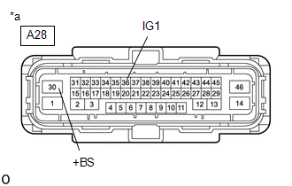
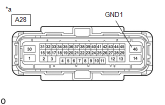
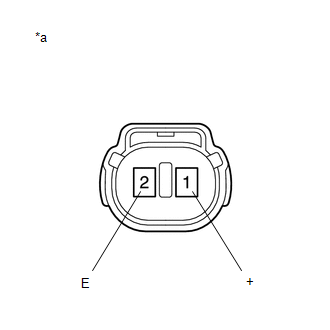
  • The skid control ECU (brake actuator assembly) connector is disconnected from the skid control ECU (brake actuator assembly).
  • The brake fluid level is insufficient.
  • The vacuum inside the brake booster decreases.
  • EBD operation is not possible.

WIRING DIAGRAM

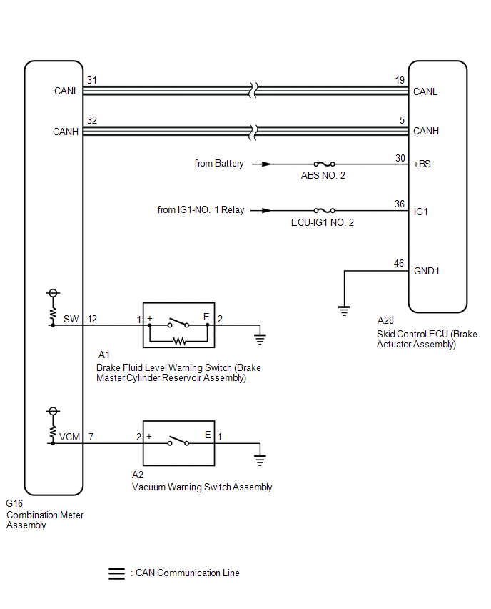
CAUTION / NOTICE / HINT

NOTICE:

  • When replacing the skid control ECU (brake actuator assembly), perform system variant learning and acceleration sensor zero point calibration.

    Click here

  • Inspect the fuses for circuits related to this system before performing the following procedure.
  • Before performing this procedure, depress the brake pedal and confirm that the stop lights illuminate.

PROCEDURE

1.

CHECK CAN COMMUNICATION SYSTEM

(a) Check if CAN communication system DTCs are output.

Click here

Result

Proceed to

DTCs are not output

A

DTCs are output

B

B

INSPECT CAN COMMUNICATION SYSTEM

A

2.

CHECK IF BRAKE ACTUATOR ASSEMBLY CONNECTOR IS SECURELY CONNECTED

(a) Check if the skid control ECU (brake actuator assembly) connector is securely connected.

OK:

The connector is securely connected.

NG

CONNECT CONNECTOR TO BRAKE ACTUATOR ASSEMBLY CORRECTLY

OK

3.

CHECK BATTERY

(a) Check the battery voltage.

Standard Voltage:

Tester Connection

Condition

Specified Condition

Positive (+) terminal - Negative (-) terminal

Engine switch off

11 to 14 V

NG

CHECK OR REPLACE CHARGING SYSTEM COMPONENT OR BATTERY

OK

4.

CHECK HARNESS AND CONNECTOR (POWER SOURCE TERMINAL)

(a) Turn the engine switch off.

*a

Front view of wire harness connector

(to Skid Control ECU (Brake Actuator Assembly))

(b) Make sure that there is no looseness at the locking part and the connecting part of the connector.

OK:

The connector is securely connected.

(c) Disconnect the A28 skid control ECU (brake actuator assembly) connector.

(d) Check both the connector case and the terminals for deformation and corrosion.

OK:

No deformation or corrosion.

(e) Measure the voltage according to the value(s) in the table below.

Standard Voltage:

Tester Connection

Condition

Specified Condition

A28-30 (+BS) - Body ground

Always

11 to 14 V

A28-36 (IG1) - Body ground

Engine switch on (IG)

11 to 14 V

NG

REPAIR OR REPLACE HARNESS OR CONNECTOR (POWER SOURCE CIRCUIT)

OK

5.

CHECK HARNESS AND CONNECTOR (GND1 TERMINAL)

(a) Turn the engine switch off.

*a

Front view of wire harness connector

(to Skid Control ECU (Brake Actuator Assembly))

(b) Measure the resistance according to the value(s) in the table below.

Standard Resistance:

Tester Connection

Condition

Specified Condition

A28-46 (GND1) - Body ground

Always

Below 1 Ω

NG

REPAIR OR REPLACE HARNESS OR CONNECTOR (GND1 CIRCUIT)

OK

6.

INSPECT BRAKE MASTER CYLINDER RESERVOIR ASSEMBLY

(a) Turn the engine switch off.

*a

Component without harness connected

(Brake Fluid Level Warning Switch (Brake Master Cylinder Reservoir Assembly))

(b) Reconnect the A28 skid control ECU (brake actuator assembly) connector.

(c) Remove the reservoir filler cap and strainer.

(d) Make sure that there is no looseness at the locking part and the connecting part of the connector.

OK:

The connector is securely connected.

(e) Disconnect the A1 brake fluid level warning switch (brake master cylinder reservoir assembly) connector.

(f) Check both the connector case and the terminals for deformation and corrosion.

OK:

No deformation or corrosion.

(g) Measure the resistance according to the value(s) in the table below.

HINT:

A float is located inside the reservoir. Its position changes according to the brake fluid level.

Standard Resistance:

Tester Connection

Condition

Specified Condition

1 (+) - 2 (E)

Switch off (float up)

1.9 to 2.1 kΩ

1 (+) - 2 (E)

Switch on (float down)

Below 1 Ω

(h) If there is no problem after finishing the above check, adjust the brake fluid level to the MAX level.

NG

REPLACE BRAKE MASTER CYLINDER RESERVOIR ASSEMBLY

OK

7.

CHECK HARNESS AND CONNECTOR (COMBINATION METER ASSEMBLY - BRAKE MASTER CYLINDER RESERVOIR ASSEMBLY)

(a) Make sure that there is no looseness at the locking part and the connecting part of the connector.

OK:

The connector is securely connected.

(b) Disconnect the G16 combination meter assembly connector.

(c) Check both the connector case and the terminals for deformation and corrosion.

OK:

No deformation or corrosion.

(d) Measure the resistance according to the value(s) in the table below.

Standard Resistance:

Tester Connection

Condition

Specified Condition

G16-12 (SW) - A1-1 (+)

Always

Below 1 Ω

G16-12 (SW) or A1-1 (+) - Body ground

Always

10 kΩ or higher

A1-2 (E) - Body ground

Always

Below 1 Ω

NG

REPAIR OR REPLACE HARNESS OR CONNECTOR

OK

8.

INSPECT VACUUM WARNING SWITCH ASSEMBLY

(a) Reconnect the A1 brake fluid level warning switch (brake master cylinder reservoir assembly) connector.

(b) Reconnect the G16 combination meter assembly connector.

(c) Inspect the vacuum warning switch assembly.

Click here

OK:

The vacuum warning switch assembly is normal.

NG

REPLACE VACUUM WARNING SWITCH ASSEMBLY

OK

9.

CHECK HARNESS AND CONNECTOR (COMBINATION METER ASSEMBLY - VACUUM WARNING SWITCH ASSEMBLY)

(a) Make sure that there is no looseness at the locking part and the connecting part of the connector.

OK:

The connector is securely connected.

(b) Disconnect the A2 vacuum warning switch assembly connector.

(c) Disconnect the G16 combination meter assembly connector.

(d) Check both the connector case and the terminals for deformation and corrosion.

OK:

No deformation or corrosion.

(e) Measure the resistance according to the value(s) in the table below.

Standard Resistance:

Tester Connection

Condition

Specified Condition

G16-7 (VCM) - A2-2 (+)

Always

Below 1 Ω

G16-7 (VCM) or A2-2 (+) - Body ground

Always

10 kΩ or higher

A2-1 (E) - Body ground

Always

Below 1 Ω

NG

REPAIR OR REPLACE HARNESS OR CONNECTOR

OK

10.

READ VALUE USING TECHSTREAM (BRAKE WARNING LIGHT)

(a) Reconnect the A2 vacuum warning switch assembly connector.

(b) Reconnect the G16 combination meter assembly connector.

(c) Enter the following menus: Chassis / ABS/VSC/TRAC/EPB / Data List.

Chassis > ABS/VSC/TRAC/EPB > Data List

Tester Display

Measurement Item

Range

Normal Condition

Diagnostic Note

Brake Warning Light

Brake system warning light (red indicator)

ON or OFF

ON: Warning light on

OFF: Warning light off

-

Chassis > ABS/VSC/TRAC/EPB > Data List

Tester Display

Brake Warning Light

(d) Check the Techstream display condition of the brake system warning light (red indicator).

Result

Proceed to

The value of Brake Warning Light is ON

A

The value of Brake Warning Light is OFF

B

A

REPLACE BRAKE ACTUATOR ASSEMBLY

B

INSPECT METER / GAUGE SYSTEM

    Brake Warning Light does not Come ON

    Open Circuit in ABS Motor Relay Circuit (C146C)

    See More:

    Toyota Avalon Service & Repair Manual > Park Assist / Monitoring: Television Camera(for Front)
    ComponentsCOMPONENTS ILLUSTRATION *A for Bar Type Radiator Grille *B for Mesh Type Radiator Grille *1 COOL AIR INTAKE DUCT SEAL *2 FRONT TELEVISION CAMERA ASSEMBLY InstallationINSTALLATION PROCEDURE 1. INSTALL FRONT TELEVISION CAMERA ASSEMBLY (a) Engage the 2 guides. (b) Install the front televisio ...

    Toyota Avalon Owners Manual

    Toyota Avalon Service & Repair Manual

    © 2024 Copyright www.tavalon.net
    0.0195